Transcription of Application Note: Determining the Circuit Breaker Size
1 Application Note: Determining the Circuit Breaker Size 1. Application Note: Determining the Circuit Breaker Size Revision History Version September 2021: Changes in Circuit Breaker criteria table Version July 2021: More info added to Circuit Breaker criteria table Version January 2021: More info added to Circuit Breaker criteria table Version February 2019: release Introduction Inverters should be protected by Circuit breakers. This document describes how to determine which Circuit Breaker to use in three phase commercial installations. Using Transformers in Commercial Three Phase Inverter Installations Using transformers in a commercial installation is optional. In most cases a transformer is used to connect the installation to the medium voltage power grid.
2 For an example of how to connect a transformer on a medium voltage power grid, refer to: Medium Voltage Transformer Connection of Commercial Systems, North America Medium Voltage Transformer Connection of Commercial Systems The following figure illustrates a typical transformer and commercial three phase inverter installation topology. Figure 1: Typical transformer and commercial three phase inverter installation topology There are many considerations for selecting the suitable transformer and its associated current limiting devices such as Circuit breakers and fuses. The considerations must include at least the following: The transformer should be designed for a typical PV system production profile: high daytime loads with no loads at night.
3 The current limiting devices should protect the electrical circuits and the inverters from the excess current created by an overload, or a short Circuit . If a short Circuit or other overcurrent occurs, the current limiting devices should block the current flow to the Circuit , thus preventing damage to the electrical circuits and the inverters. The Circuit breakers and the fuses should comply with the transformer manufacturer recommendations and with the relevant sections in standards such as IEC 60909 , IEC 60364, UL 508A and NEC 2017. Some manufacturers provide detailed information about the transformer short Circuit calculation procedure, and its effect on the selection of Circuit breakers and fuses at the different hierarchical levels of the installation topology (see Figure 1).
4 For an example of a calculation, refer to: Application Note: Determining the Circuit Breaker Size Application Note: Determining the Circuit Breaker Size 2. Guidelines on the Short Circuit Current Rating for Industrial Control Panels Short- Circuit current rating (SCCR) of industrial control panels To ensure that the Circuit Breaker and fuses trip as expected, follow their manufacturers' recommendations, especially with respect to the various de-rating considerations. NOTE. Transformer procurement, installation, maintenance and support are the responsibility of the installer. Damage to the inverter due to incorrect transformer installation, or use of a transformer that is incompatible with the SolarEdge system will render the SolarEdge warranty invalid.
5 Determining the Size of an Inverter Circuit Breaker This section explains how to determine the rate of a Circuit Breaker next to an inverter. For an example of an inverter with a Circuit Breaker next to it see Figure 1. Ensure you have the following parameters before Determining the Circuit Breaker size: The inverter's maximum continuous output current as appears in the data-sheet. Factor for the installation's country. This factor is dictated by regulation, applicable standards or common practice and is usually To determine the size of an inverter Circuit Breaker : 1. Multiply the inverter's maximum continuous output current by the factor. For example, 40A x 50A. 2. Round up the rated size, as calculated in step 1, to the closest standard Circuit Breaker size.
6 See Circuit Breaker Criteria table below for standard sizes suitable for SolarEdge three phase inverters. NOTE. If the result has a decimal fraction smaller than round it down. 3. To ensure that the selected Circuit Breaker trips as expected, at minimum consider the following: The Circuit Breaker rated Voltage and current. Temperature de-rating due to both close proximity of other Circuit breakers and the effect of ambient temperature on the distribution board. De-rating due to permanent load. If the de-rated current of the selected Circuit Breaker is lower than the maximum output current of the inverter, consider selecting a Circuit Breaker that is designed for a higher rated current, or reducing the temperature de-rating effect by increasing the distance between adjacent Circuit breakers.
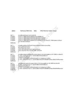
7 NOTE. Make sure to select cables that are suitable for the environmental conditions, operating Voltage, current and the selected Circuit Breaker . Three or four pole Circuit breakers are required. It is recommended to use a four pole Circuit Breaker when applicable. Calculate and verify that the Circuit Breaker is able to withstand the expected fault current. Only use a Circuit Breaker with tripping characteristic B or C. Table 1 describes the Circuit Breaker criteria. Note the table may not cover all inverters. For more information related to selecting Circuit breakers, refer to the Inverter data sheet. North America 208 L-L. Inverter Max. Continuous Output Current (per Phase) Recommended Circuit Breaker Three Phase Inverter 40A 50A.
8 63A. Three Phase Inverter with Synergy Technology 120A 150A. SE50 KUS 175A. Application Note: Determining the Circuit Breaker Size Application Note: Determining the Circuit Breaker Size 3. North America 480 L-L. Inverter Max. Continuous Output Current (per Phase) Recommended Circuit Breaker Three Phase Inverter SE30 KUS 50A. 40A 50A. SE40 KUS 63A. Three Phase Inverter with Synergy Technology 80A 100A. SE80 KUS 125A. SE100 KUS 120A 150A. SE120 KUS 145A 200A. Europe and APAC 380/400 L-L. Inverter Max. Continuous Output Current (per Phase) Recommended Circuit Breaker Three Phase Inverter 20A 25A. SE15K 23A 32A. SE16K 32A. SE17K 26A 32A. (1). SE25K 50A. 40A 50A. SE30K 63A. 63A. Three Phase Inverter with Synergy Technology SE50K 76A 100A.
9 80A 100A. 125A. SE75K 120A 150A. 120A 150A. SE90K 175A. SE100K 145A 200A. Europe and APAC 480 L-L. Inverter Max. Continuous Output Current (per Phase) Recommended Circuit Breaker Three Phase Inverter 40A 50A. SE40K 63A. Three Phase Inverter with Synergy Technology 80A 100A. SE80K 125A. SE100K 120A 150A. SE120K 145A 200A. (1)In some countries, the max. continuous output current is 38A. Please refer to the inverter DS. Application Note: Determining the Circuit Breaker Siz