Transcription of Application Note Electrolytic Tilt Sensor Basics
1 Application Note Electrolytic tilt Sensor Basics SPECTRON GLASS AND ELECTRONICS INC. 595 OLD WILLETS PATH HAUPPAUGE NY 11788 PHONE: 631 582-5600 FAX: 631 582-5671 Specifications are subject to change without notice! Doc.# SAN-201-1703 INTRODUCTION SPECTRON'S Electrolytic LEVEL ( tilt ) SENSORS are basically resistance potentiometers. They are devices and should not be exposed to currents.
2 Currents cause an electroplating action between electrodes and a precipitation (deionization) of the conducting salts in the electrolyte. As an device, with the plate-like construction of the electrodes, there is a capacitive effect within the device in addition to the resistance element. It is only necessary to address this characteristic when used at high frequencies or when excited with square waves. In mounting, it should be remembered that glass, a brittle material, fails only from tensile stresses, never from shear or compression.
3 It is to the customer's advantage to place responsibility of mounting and aligning the Sensor on Spectron. ELECTRICAL CHARACTERISTICS At low frequencies, the end to end impedance, considered resistive in nature, can be supplied in the range of 1,000 to 10,000 ohms. With today's high impedance input electronics, most customers will prefer the higher impedance units so as to minimize power drain. Scale Factor is inversely proportional to range and range inversely proportional to the radius of curvature of the inner cavity.
4 Sensitivity, or resolution is best with the sensors having the greatest radius of curvature. Equivalent Circuit: Definition of Null: R1 = R2 when level Note; when tilted away from null, capacitance as well as resistance changes. RECOMMENDED CIRCUIT USE The most accurate treatment of the Sensor in a users system is as a voltage divider or ratiometer. This is of course due to the immunity to minor changes in excitation levels. At null, or when horizontal, the ratiometer is at the setting.
5 With + and - tilts, this ratio will be altered without a phase or polarity change. CONDITIONING CIRCUIT CONSTRUCTION The most popular configuration is the Wheatstone bridge circuit. The Sensor can be used as one half the bridge with the full excitation voltage across the Sensor or as the lower half of a bridge with resistors in series with each half of the Sensor . Gyro instrument users prefer this configuration and substitute torqueing coils for the series resistors. Excitation voltage = 5 volts peak to peak Excitation frequency = 500Hz - 5 KHz Either a square or sine wave is acceptable, there is no advantage of one over the other.
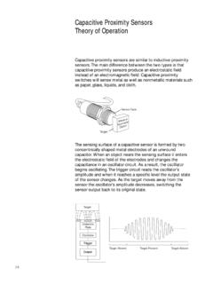
6 Tantalum capacitors are acceptable for decoupling the excitation signal. When the excitation voltage is applied to the outer electrodes, and a phase sensitive voltmeter is hooked up between the center electrode and one of the excitation electrodes, it has an output signal proportional to the tilt angle. The output is zero if the Sensor is aligned with the vertical plane. Any deviation from the alignment increases the output voltage. The tilt direction can be deduced from the phase between the excitation and center electrodes.
7 The phase varies from 0 to 180 . The output impedance for the excitation should be lower than 10 ohms, while the input impedance, which is tied to the center electrode, should be higher than 5 megohms. Application Note Electrolytic tilt Sensor Basics SPECTRON GLASS AND ELECTRONICS INC. 595 OLD WILLETS PATH HAUPPAUGE NY 11788 PHONE: 631 582-5600 FAX: 631 582-5671 Specifications are subject to change without notice!
8 Doc.# SAN-201-1703 MECHANICAL CONSIDERATIONS Of most importance is the mismatch of thermal coefficients of expansion when addressing the mounting and alignment requirements. The thermal coefficient for the glass most used is x 10-6 inches/inch/degree F. Alignment to a vertical banking surface is necessary where tilts about the non-sensitive axis are expected. Essentially, during alignment and installation in the holder the complete assembly is tilted about the defined non-sensing axis and the Sensor adjusted for no change in output.
9 Temperature sensitivity of the Sensor can be divided into two areas. The first, steady state changes, is simplest to consider. As temperature goes up, scale factor goes down, linearly. All Sensor scale factors change by per degree F as a nominal number. Generally, the variations are not significant to the customer. The second, transient temperature conditions cause the greatest difficulty when they create left to right gradients. These are significantly attenuated when a potting compound having low thermal conductivity is used to completely encapsulate the Sensor .
10