Transcription of Capacitive Proximity Sensors Theory of Operation
1 54 Capacitive Proximity SensorsTheory of OperationCapacitive Proximity Sensors are similar to inductive proximitysensors. The main difference between the two types is thatcapacitive Proximity Sensors produce an electrostatic fieldinstead of an electromagnetic field. Capacitive proximityswitches will sense metal as well as nonmetallic materials suchas paper, glass, liquids, and sensing surface of a Capacitive sensor is formed by twoconcentrically shaped metal electrodes of an unwoundcapacitor. When an object nears the sensing surface it entersthe electrostatic field of the electrodes and changes thecapacitance in an oscillator circuit. As a result, the oscillatorbegins oscillating. The trigger circuit reads the oscillator samplitude and when it reaches a specific level the output stateof the sensor changes. As the target moves away from thesensor the oscillator s amplitude decreases, switching thesensor output back to its original Target andStandard targets are specified for each Capacitive sensor .
2 TheDielectric Constantstandard target is usually defined as metal and/or Sensors depend on the dielectric constant of thetarget. The larger the dielectric number of a material the easier itis to detect. The following graph shows the relationship of thedielectric constant of a target and the sensor s ability to detectthe material based on the rated sensing distance (Sr).The following table shows the dielectric constants of somematerials. If, for example, a Capacitive sensor has a ratedsensing distance of 10 mm and the target is alcohol, theeffective sensing distance (Sr) is approximately 85% of therated distance, or ConstantMaterialDielectric Polystyrene3 Mica6 Polyvinyl Rubber4 Silica Casting Silica , Vacuum1 Silicone Teflon2 Oil-Impregnated Paper4 Turpentine Transformer W at Soft Celluloid356 Detection Through BarriersOne application for Capacitive Proximity Sensors is leveldetection through a barrier.
3 For example, water has a muchhigher dielectric than plastic. This gives the sensor the ability to see through the plastic and detect the Siemens Capacitive Sensors are shielded. These Sensors willdetect conductive material such as copper, aluminum, orconductive fluids, and nonconductive material such as glass,plastic, cloth, and paper. Shielded Sensors can be flushmounted without adversely affecting their sensingcharacteristics. Care must be taken to ensure that this type ofsensor is used in a dry environment. Liquid on the sensingsurface could cause the sensor to Proximity sensor FamilyThe 3RG16 product family identifies the Siemens capacitiveproximity sensor . Units are available in DC or AC controls such as SIMATIC PLCs or relays can becontrolled directly with the DC voltage version. In the case ofthe AC voltage version the load (contactor relay, solenoid valve)is connected with the sensor in series directly to the ACvoltage.
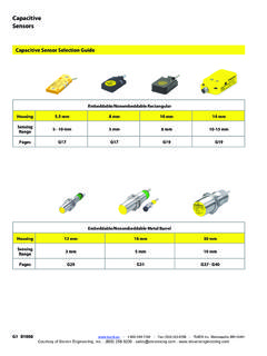
4 Sensors are available with two-, three-, and SensorSelection GuideHousing Dimension (m m)MaterialShielded Unshie lde dSn (mm)Operating VoltageWires18 PlasticShielded510-65 VDC3 MetalShielded1020-250 VAC3 PlasticShielded1020-250 VAC2 MetalShielded1010-65 VDC4 PlasticShielded1010-65 VDC4 PlasticShielded2020-250 VAC2 PlasticShielded2010-65 VDC4 PlasticShielded2020-250 VAC2 PlasticShielded2010-65 VDC420x20 (Flat Pack)MetalShielded510-30 VDC33040x40 (Limit Switch Style)4058 Review 41)A main difference between an inductive proximitysensor and a Capacitive Proximity sensor is that acapacitive Proximity sensor produces an ) Capacitive Proximity Sensors will sense )The larger the _____ constant of a material theeasier it is for a Capacitive Proximity sense to )It is easier for a Capacitive Proximity sensor to detect_____ than teflonb. marblec. petroleumd. paper5)The maximum rated sensing distance of a capacitiveproximity sensor is _____ Proximity SensorsTheory of OperationUltrasonic Proximity Sensors use a transducer to send andreceive high frequency sound signals.
5 When a target enters thebeam the sound is reflected back to the switch, causing it toenergize or deenergize the output DiskA piezoelectric ceramic disk is mounted in the sensor surface. Itcan transmit and receive high-frequency pulses. A high-frequency voltage is applied to the disk, causing it to vibrate atthe same frequency. The vibrating disk produces high-frequencysound waves. When transmitted pulses strike a sound-reflectingobject, echoes are produced. The duration of the reflected pulseis evaluated at the transducer. When the target enters thepreset operating range, the output of the switch changes the target leaves the preset operating range, the outputreturns to its original emitted pulse is actually a set of 30 pulses at an amplitudeof 200 Kvolts. The echo can be in ZoneA blind zone exists directly in front of the sensor . Depending onthe sensor the blind zone is from 6 to 80 cm.
6 An object placedin the blind zone will produce an unstable DefinitionThe time interval between the transmitted signal and the echois directly proportional to the distance between the object andsensor. The operating range can be adjusted in terms of itswidth and position within the sensing range. The upper limit canbe adjusted on all Sensors . The lower limit can be adjusted onlywith certain versions. Objects beyond the upper limit do notproduce a change at the output of the sensor . This is known as blanking out the background .On some Sensors , a blocking range also exists. This is betweenthe lower limit and the blind zone. An object in the blockingrange prevents identification of a target in the operating is a signal output assigned to both the operating rangeand the output PatternThe radiation pattern of an ultrasonic sensor consists of a maincone and several neighboring cones. The approximate angle ofthe main cone is 5.
7 Free ZonesFree zones must be maintained around the sensor to allow forneighboring cones. The following examples show the free arearequired for different SensorsIn the first example, two sonar Sensors with the same sensingrange have been mounted parallel to each other. The targets arevertical to the sound cone. The distance between the Sensors isdetermined by the sensing range. For example, if the sensingrange of the Sensors is 6 cm, they must be located at least15 cm r g e tTa r g e tSensing Range (CM)X (CM)6-30>1520-130>6040-300>15060-600>250 80-1000>35062 Mutual InterferenceMutual interference occurs when sonar devices are mounted inclose Proximity to each other and the target is in a position toreflect echoes back to a sensor in the Proximity of thetransmitting sensor . In this case, the distance between Sensors (X) can be determined through SensorsIn the following example, two sonar Sensors with the samesensing range have been positioned opposite of each other.
8 Aminimum distance (X) is required between opposing Sensors sothat mutual interferance does not Range (CM)X (CM)6-30>12020-130>40040-300>120060-600> 250080-1000 >400063 Flat and IrregularSonar Sensors mounted next to a flat surface, such as a wall orShaped Surfacessmooth machine face, require less free area than sensorsmounted next to an irregular shaped AlignmentThe angle of the target entering the sound cone must also beconsidered. The maximum deviation from the send direction toa flat surface is 3 .If the angle were greater than 3 the sonic pulses would bereflected away and the sensor would not receive an Range (CM)X (CM)Y (CM)6-130>3>620-130>15>3040-300>30>6060- 600>40>8080-1000>70>15064 Liquids andLiquids, such as water, are also limited to an angular alignmentCoarse-Grained Materialsof 3 . Coarse-grained materials, such as sand, can have anangular deviation as much as 45 . This is because the sound isreflected over a larger angle by coarse-grained Out ObjectsAn object may be located in the vicinity of the sound cone thatcauses improper operating of the sensor .
9 These objects can beblanked out by using an aperture made of a sound absorbingmaterial such as rock wool. This narrows the sound cone andprevents pulses from reaching the interfering object. 65 Operating ModesSonar Sensors can be setup to operate in several differentmodes: diffuse, reflex, and ModeThis is the standard mode of Operation . Objects, traveling in anydirection into the operating range of the sound cone, will causethe sensor output to switch states. This mode of Operation issimilar to a Proximity ModeThe reflex mode uses a reflector located in the preset operatingrange. The operating range is adjusted for the reflector. Thepulses are bounced off the reflector and the echo pulses arereturned to the sensor . When a target blocks the echo pulsesthe output is activated. Typically used in applications where thetarget is not a good sound ModeThru-beam Sensors consist of a transmitter, which emitsultrasonic pulses, and a receiver.
10 If the beam between thetransmitter and the receiver is interrupted the output of thereceiver switches InfluencesSound travel time can be affected by physical properties of theair. This, in turn, can affect the preset operating distance of wave speed changes by K. Most Sensors have a compensation normal atmospheric variation of 5%, sound velocity varies approximately Sound velocity decreases between sea level and 3 km above sea level. Adjust sensor for appropriate operating will not operate in a velocity increases as humidity increases. This leads to the impression of a shorter distance to the target. The increase of velocity from dry to moisture-saturated air is up to 2%.Wind Speed<50 km/h - No Effect50 - 100 km/h - Unpredictable Results>100 km/h - No Echo Received by SensorGasSensors are designed for Operation in normal atmospheric conditions. If Sensors are operated in other types of atmospheres, such as carbon dioxide, measuring errors will or snow of normal density does not impair the Operation of a sensor .