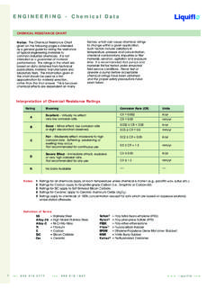
Transcription of Application Note to the Field Why Use Relief Valves?
1 Application Note to the Field Why Use Relief valves ? Application Note Number: 0108-1 Date: August 7, 2001; Revised Aug. 2008. Positive displacement pumps, which are what gear pumps are, should not be deadheaded, as they will break immediately. The exception to this for gear pumps is when the viscosity is so low that the fluid slipping backwards through the pump is actually relieving it (giving the fluid somewhere to go). In this case, the pump will most likely still fail, but for different reasons and not immediately. What typically causes gear pumps to mechanically fail (excepting those due to heat or as directly related to the chemical) is torque, which is the result of the combination of differential pressure and viscosity. When the total torque exceeds the value that the weakest component can transmit, that part fails, which will eventually cause the pump to fail.
2 It is important to understand that gear pumps do not actually make pressure, but rather move fluid. The pressure is a result of resistance to the fluid flowing through the piping system and/or some external source. If you have any viscosity at all (for the sake of argument let's say 10 cP), you have negated almost all slip, and since the gear pump is attempting to positively displace the fluid from the suction to the discharge side, the pressure will spike. Theoretically, a closed valve offers infinite resistance, so likewise the pressure would attempt to go to infinity. Needless to say, this cannot happen, so as the pressure rapidly rises, there will come a point at which the total torque is enough to break something. Usually the idler gear (if Teflon, Ryton or carbon) will have a tooth or teeth sheared off, or the drive shaft or a key will fail in shear at a stress concentration point such as the end of a keyway or a retaining ring groove.
3 In the case above, the pump would be failing somewhere on the way up the rising torque curve. It is difficult to predict at exactly what pressure and to what part a failure would occur in a particular Application . This is because materials of construction have varying strengths, there are production differences, and because viscosity plays a role in overall torque. A good analogy to the above is that if we assume a Newtonian (and therefore incompressible) fluid, deadheading is equivalent to jamming a steel bar into the gears of the running pump. It has to come to more of an abrupt stop than it can without suffering from deceleration trauma. In systems run by PLC's, it is common for the valve after the pump to be shut when the pump power is cut off. If the pump is not allowed sufficient time to slow to a stop by itself, you are stopping the pump by once again putting the steel bar into it.
4 While this may not break it right away, as the pump may be mostly stopped already, damage is cumulative. In order to prevent the above, Liquiflo recommends the use of Relief valves downstream of our pumps and before any other valves (or devices that might shut off flow). We manufacture two such valves in -inch and 1-inch sizes, and in 316 SS and Alloy-C. These valves are meant to protect the pumps only, and not to be used as control or throttling valves . While every effort is made to ensure that they are leak free (past the valve seat and to the return piping there should be no leaking to the valve exterior), they were not originally intended to be bubble tight. In the event of a fluid with a viscosity lower than that of water at 20 C (how they are tested), there may be some weeping past the internal seal. 443 North Avenue, Garwood, NJ 07027, USA Phone (908) 518-0777 Fax (908) 518-1847.
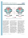
5 Liquiflo Application Note to the Field : Why Use Relief valves ? As a general rule, Liquiflo recommends that Relief valves be piped back to the supply tank, not the pump suction (see diagram below). This is to ensure that should the pump be left running in a relieved condition, it does not overheat. Overheating might occur when heat added as mechanical energy does not have enough opportunity to dissipate before being fed back into the pump. Since it is now entering at an elevated temperature and then having yet more energy added, it could turn into a runaway . condition (viscosity falls as temperature rises, slip increases and there is more running contact, or friction, etc.). If the supply tank is of insufficient size, fluid heat capacity is low, etc., there may still be a problem, but it is much less likely. Relief Relief valve should directly Valve bypass discharge line back to supply tank, as shown Supply Tank Ps Pd Isolation Gear Throttle Flow to Valve Pump Valve Process 10 standard Liquiflo Relief Valve models are available, depending on the body material, the port size and the pressure setting range (see table below).
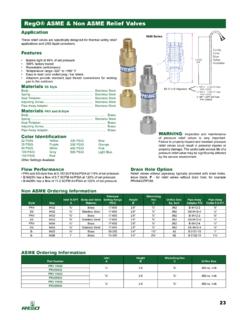
6 Models RV1000, RV1001, RV2000 and RV2001 are factory preset to discharge at 100 PSI; however, a different pressure setting can be requested. For the LP and HP models, the pressure setting must be specified when ordering. Each model has the feature of being Field -adjustable to any pressure setting within its respective range. The design features of the Liquiflo Relief Valve are shown on the following page. LIQUIFLO Relief valves Models & Specifications Port Size Pressure Approximate Flow @ 25%. Model # Material Setting (PSI) above Pressure Setting & Type Min Max USGPM LPM. RV1000-LP 316 SS NPT 25 65 28. RV1000 316 SS NPT 50 135 28. RV1000-HP 316 SS NPT 75 200 28. RV1001-LP Alloy-C NPT 25 65 28. RV1001 Alloy-C NPT 50 135 28. RV1001-HP Alloy-C NPT 75 200 28. RV2000-LP 316 SS 1 NPT 25 75 25 95. RV2000 316 SS 1 NPT 50 175 25 95.
7 RV2001-LP Alloy-C 1 NPT 25 75 25 95. RV2001 Alloy-C 1 NPT 50 175 25 95. LP = Low Pressure HP = High Pressure 443 North Avenue, Garwood, NJ 07027, USA Phone (908) 518-0777 Fax (908) 518-1847. Liquiflo Application Note to the Field : Why Use Relief valves ? LIQUIFLO Relief VALVE Design Features Adjusting Cap Internal Spring Cap Discharge pressure adjustment Retains Spring in can be performed while the conjunction with Lock Pin Relief Valve is in service (matches metallurgy of without leakage Relief Valve Body). Safety Lock Pin Lock Nut Ensures parts will not separate Locks Adjusting even if Adjusting Cap is Cap in place removed Teflon O-Ring Body Gives Liquiflo Relief Valve Available in 316 SS a unique advantage by or Alloy-C allowing adjustment while in service without leakage Spring Determines discharge Outlet pressure setting range or 1 NPT.
8 (matches metallurgy of Relief Valve Body). Valve Pin Opens when discharge pressure exceeds pressure setting (matches metallurgy Inlet of Relief Valve Body). or 1 NPT. 443 North Avenue, Garwood, NJ 07027, USA Phone (908) 518-0777 Fax (908) 518-1847.