Transcription of Application Note Volume and Surface Resistivity ...
1 Volume and Surface Resistivity Measurementsof Insulating Materials Using the Model 6517 AElectrometer/High Resistance MeterIntroductionA fundamental property of insulators is Resistivity . Theresistivity may be used to determine the dielectric breakdown,dissipation factor, moisture content, mechanical continuity andother important properties of a material. The Volume resistivityof some insulators, such as sapphire and Teflon , can be as highas 1016 to 1018 ohm-cm. Because of such large magnitudes,measuring the Resistivity of insulators can be difficult unlessproper test methods and instrumentation are used. One testmethod often used for measuring Resistivity of insulators isASTM D-257, DC Resistance or Conductance of InsulatingMaterials.
2 Instruments called electrometers are used to make thismeasurement because of their ability to measure small and TechniquesThe Resistivity of an insulator is measured by sourcing aknown voltage, measuring the resulting current, and calculatingthe resistance using Ohm s Law. From the resistance measure-ment, the Resistivity is determined based on the physical dimen-sions of the test Resistivity is dependent on several factors. First, it is afunction of the applied voltage. Sometimes the voltage may bevaried intentionally to determine an insulator s voltage depend-ence. The Resistivity also varies as a function of the length ofelectrification time. The longer the voltage is applied, the higherthe Resistivity because the material continues to charge exponen-tially.
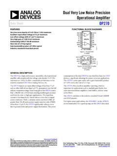
3 Environmental factors also affect an insulator s general, the higher the humidity, the lower the Resistivity . Tomake accurate comparisons to a specific test, the applied voltage,electrification time, and environmental conditions should be keptconstant from one test to the next. According to the ASTM standard, a commonly used test condition is a voltage of 500 Vapplied for 60 upon the Application , the Volume or the surfaceresistivity, or both, is ResistivitySurface Resistivity is defined as the electrical resistance ofthe Surface of an insulator material. It is measured fromelectrode to electrode along the Surface of the insulator the Surface length is fixed, the measurement is independentof the physical dimensions ( , thickness and diameter) of theinsulator pElectrodeRingElectrodeGuard6517AV-Sourc eHILOHILOA6517 APicoammeterFigure 1.
4 Surface resisitivity measurement techniqueSurface Resistivity is measured by applying a voltagepotential across the Surface of the insulator sample and measuringthe resultant current as shown in Figure 1. The Model 6517 Aautomatically performs the following calculation and displays thesurface Resistivity reading: S = KSR S= Surface Resistivity (per square)R = measured resistance in ohms (V/I)KS= P/gwhere:P = the effective perimeter of the guarded electrode (mm)g = distance between the guarded electrode and the ring electrode(mm). Refer to Figure 2 to determine dimension circular electrodes:P = D0D0 = D1 + g (refer to Figure 2 to determine dimension D0). Volume ResistivityVolume Resistivity is defined as the electrical resistancethrough a cube of insulating material.
5 When expressed in ohm-centimeters, it would be the electrical resistance through a one-centimeter cube of insulating material. If expressed in ohm-inches, it would be the electrical resistance through a one-inchcube of insulating NoteSeriesNumber 314 Standard Method Resistivity Tests( Surface and Volume )This test is used to measure the Resistivity ( Surface orvolume) of an insulator sample. When used with the Model 8009 Resistivity Test Fixture, the test conforms to the ASTM D-257standard. Figures 1 and 3 show the test circuits for the respectivemeasurements, and Figure 4 shows the connections to the Model8009. Refer to the instruction manual for the Model 8009 toinstall the insulator sample in the test this test is run, the V-Source will initially be set tosource 0V for a specified time (PRE-DISCH time) to allow anycharge to dissipate.
6 The V-Source will then apply a specifiedvoltage (BIAS V) to the electrodes of the test fixture for aspecified time (BIAS-TIME). This bias period allows currentsin the test circuit to stabilize. The V-Source then applies the testvoltage (MEAS-V) and, after a specified delay (MEAS-TIME),the Model 6517A measures the Resistivity of the sample andstores the reading in the buffer. Note that the test voltage (MEAS-V) is typically at the same level as the bias voltage (BIAS-V).The Surface Resistivity Test and the Volume ResistivityTest are selected and configured from the CONFIGURESEQUENCE menu (R/ Resistivity ; NORMAL; SURFACEand Volume ).Alternating Polarity Resistance/ Resistivity TestThe Alternating Polarity Resistance/ Resistivity test isdesigned to improve high resistance/ Resistivity measurements are prone to large errors due to backgroundcurrents.
7 By using an alternating stimulus voltage, it is possible toeliminate the effects of these background currents. This test willmeasure Surface or Volume Resistivity or resistance, as selected inthe CONFIGURE RESISTANCE menu. Figures 1 and 3 showthe test circuits for the respective measurements, and Figure 4shows the connections to the Model 8009. Refer to the Model8009 Instruction Manual for information on installing the samplein the test this test is run, the V-Source will alternate betweentwo voltages (V-OFS + V-ALT) and (V-OFS - V-ALT) at timedintervals (MEAS-TIME). Current measurements are taken at theend of each of these alternations and after calculation of Icalcresistance values are computed.
8 Icalc is a weighted average of thelatest four current measurements, each at the end of a separatealternation. The resistance value is then converted to a resistivityvalue if the meter has been configured for Resistivity measure-ments. The first few readings can be rejected (DISCARD XXXRDGS) as the sample or resistance achieves a steady-stateresponse to the alternating voltage. After this, the alternation willcontinue until a specified number of readings (STORE XXXRDGS) have been stored in the buffer. The time required tocomplete a sequence is (STORE + DISCARD + 4) MEAS-TIME. For example, a sequence alternating at 15 second inter-vals, discarding three readings, and storing three readings willtake 5 shows an example of the Alternating Polarity testusing the test parameters shown and the resulting sample currentfrom a typical high resistance sample.
9 Note that the samplecurrents shown exhibit some capacitive delay, as many highresistance samples also tend to have significant 6517 AWARNING:NO INTERNAL OPERATOR SERVICABLE PARTS,SERVICE BY QUALIFIED PERSONNEL :NO INTERNAL OPERATOR SERVICABLE PARTS,SERVICE BY QUALIFIED PERSONNEL :FOR CONTINUED PROTECTION AGAINST FIRE HAZARD,REPLACE FUSE WITH SAME TYPE AND :FOR CONTINUED PROTECTION AGAINST FIRE HAZARD,REPLACE FUSE WITH SAME TYPE AND LIDINTERLOCKTRIAX250 MAXHI-LOMAX INPUT1100V!INPUT250V PEAKCOMMONOUT!LINE RATING90-134 VAC180-250 VAC50, 60, 400HZ55VA MAXLINE FUSESLOWBLOW1/2A, 250 VIEEE-488(CHANGE IEEE ADDRESSWITH FRONT PANEL MENU)PREAMP OUT250V PEAKV SOURCELOHIINTERLOCK!
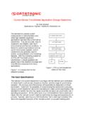
10 Warning: Connect of fixture to safety earth ground using safety ground wire (supplied with 8002A test fixture).7078-TRX-3 Triax Cable8607 Banana Plug Cables6517-ILC-3 Interlock CableModel 8009 Figure 4. Connections for measurements using Model 8009 Test FixtureTest FixtureDimensions (cm)Model inD1D0D2gRingElectrodeGuardedElectrodeD0 = D1 + gg =D1 D22 SampleD1D0D2 RingElectrodeGuardedElectrodegFigure 2. Circular electrode dimensionsVolume Resistivity is measured by applying a voltagepotential across opposite sides of the insulator sample andmeasuring the resultant current through the sample as shown inFigure 3.