Transcription of APPLICATIONS FEATURES & BENEFITS
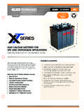
1 UPSV alve Regulated Lead Acid BatteryDesigned for UPS Standby Power Data Centers Network Operations Centers Industrial Process Control Facilities Internet Housing Sites Semiconductor Manufacturing Banks & Financial Markets Power Generation Plants Hospitals & Testing Laboratories Emergency 911 Response Centers 10 year design life @ 25 C Absorbent Glass Mat (AGM) technology for efficient gas recombination of up to 99% and freedom from electrolyte maintenance. Patented Long Life Alloy having the lowest calcium levels in the industry - minimizing grid growth, reducing gassing, and extending battery life. Patented UL Recognized Flame- arresting vents in each cell for safety and long life.
2 Designed with the same recombination, thermal runaway prevention, gassing and flame retardant characteristics of the Bellcore 4228 compliant Dynasty Telecom products. Flame retardant polypropylene case and cover compliant with UL94-V2 Thermally welded case-to-cover bond to eliminate leakage. Can be operated in any orientation. Upright, side or end mounting recommended. Not restricted for air transport - Complies with IATA/ICAO Special Provisions A67. Not restricted for surface transport - Classified as non-hazardous material as related to DOT-CFR Title 49 parts 171-189. Not restricted for water transport - Classified as non-hazardous material per IMDG Amendment 27.
3 * Nominal 20 hr rate to VPC in & BENEFITS TECHNICAL DATAM odelVoltageAH20 hr*Constant Power Discharge Ratings - Watts per Cell @ +77 F (+25 C)WeightOperating Time (in minutes) to Volts per *All dimensions in inches (mm). All dimensions are for reference only. Contact a C&D Representative for complete dimension information. NOTE: Batteries to be mounted with in ( cm) spacing minimum and free air 12-300 MRUPS12-150 MRBattery ( ) ( ) ( ) ( ) ( ) ( ) ( ) ( ) ( ) ( ) ( ) ( ) ( ) ( ) ( ) ( ) ( ) ( ) ( ) ( ) ( ) ( ) ( ) ( ) ( ) ( ) ( ) ( ) ( ) ( ) ( ) ( ) ( ) ( ) ( ) ( ) ( ) ( ) ( ) ( ) ( ) ( ) ( ) ( ) ( ) ( ) ( ) ( ) #10-32 #10-32 UNF12-1029/0915/CD 2 Temperature Rangewith temperature compensationDischarge: -40 F (-40 C) to +160 F (+71 C)Charge.
4 -10 F (-23 C) to +140 F (+60 C)Nominal Operating Temperature Range+74 F (23 C) to +80 F (27 C)Recommended Maximum ChargingCurrent LimitC20/5 amperes @ 20hr rateFloat Charging VDC average per 12V unit ( to per 6V unit)Maximum AC Ripple (Charger) RMS or P-P of float charge voltage recommended for best voltage allowed = RMS (4% P-P) Max current allowed = C/20 @ 20 hr. rateSelf DischargeBattery can be stored up to 6 months at 77 F (25 C) before a freshening charge is required. Batteries stored at temperatures greater than 77 F (25 C) will require recharge sooner than batteries stored at lower temperatures. See C&D brochure 41-7272, Self-Discharge and Inventory Control for charge and cycle service to VDC average per 12V unit @ 77 F (25 C) ( to VDC per 6V unit.)
5 Terminal: in. clearance hole to accept in. or 10-32 bolt (UPS12-100MR)Terminal: InsertedThreaded copper alloy insert terminal to accept 10-32 UNF bolt (UPS12-150MR, UPS12-210MR) 1 4-20 UNC bolt (UPS12-300MR, UPS12-350MR, UPS12-400MR, UPS12-490MR, UPS12-540MR, UPS6-620MR)Terminal Hardware Annual Retorque32 ( N-m) (UPS12-100MR)Terminal Hardware Initial Torque:Inserted Terminal40 ( N-m) (UPS12-100MR)30 ( N-m) (UPS12-150MR, UPS12-210MR) 110 ( N-m) (UPS12-300MR, UPS12-350MR, UPS12-400MR, UPS12-490MR,UPS12-540MR, UPS6-620MR)SPECIFICATIONSDIMENSIONSNote: Batteries to be mounted with in. ( cm) spacing minimum and free air ventilation. Specifications subject to change without notification.
6 Above ratings do not include interunit connector voltage 3 : Batteries to be mounted with in. ( cm) spacing minimum and free air ventilation. Specifications subject to change without notification. Above ratings do not include interunit connector voltage : Batteries to be mounted with in. ( cm) spacing minimum and free air ventilation. Specifications subject to change without notification. Above ratings do not include interunit connector voltage Point Volts/CellConstant Power Discharge Ratings - Watts Per Cell @ +77 F (+25 C)Operating Time to End Point Voltage (in minutes) Point Volts/CellConstant Current Discharge Ratings - Amps Per Cell @ +77 F (+25 C)Operating Time to End Point Voltage (in hours).
7 Point Volts/CellConstant Power Discharge Ratings - Watts Per Cell @ +77 F (+25 C)Operating Time to End Point Voltage (in minutes) Point Volts/CellConstant Current Discharge Ratings - Amps Per Cell @ +77 F (+25 C)Operating Time to End Point Voltage (in hours) Point Volts/CellConstant Power Discharge Ratings - Watts Per Cell @ +77 F (+25 C)Operating Time to End Point Voltage (in minutes) Point Volts/CellConstant Current Discharge Ratings - Amps Per Cell @ +77 F (+25 C)Operating Time to End Point Voltage (in hours) : Batteries to be mounted with in. ( cm) spacing minimum and free air ventilation. Specifications subject to change without notification. Above ratings do not include interunit connector voltage : Batteries to be mounted with in.
8 ( cm) spacing minimum and free air ventilation. Specifications subject to change without notification. Above ratings do not include interunit connector voltage : Batteries to be mounted with in. ( cm) spacing minimum and free air ventilation. Specifications subject to change without notification. Above ratings do not include interunit connector voltage 4 Point Volts/CellConstant Power Discharge Ratings - Watts Per Cell @ +77 F (+25 C)Operating Time to End Point Voltage (in minutes) Point Volts/CellConstant Current Discharge Ratings - Amps Per Cell @ +77 F (+25 C)Operating Time to End Point Voltage (in hours) Point Volts/CellConstant Power Discharge Ratings - Watts Per Cell @ +77 F (+25 C)Operating Time to End Point Voltage (in minutes) Point Volts/CellConstant Current Discharge Ratings - Amps Per Cell @ +77 F (+25 C)Operating Time to End Point Voltage (in hours) Point Volts/CellConstant Power Discharge Ratings - Watts Per Cell @ +77 F (+25 C)
9 Operating Time to End Point Voltage (in minutes) Point Volts/CellConstant Current Discharge Ratings - Amps Per Cell @ +77 F (+25 C)Operating Time to End Point Voltage (in hours) : Batteries to be mounted with in. ( cm) spacing minimum and free air ventilation. Specifications subject to change without notification. Above ratings do not include interunit connector voltage product details available on the C&D Battery Sizing Program at Cabinet systems also 5 : Batteries to be mounted with in. ( cm) spacing minimum and free air ventilation. Specifications subject to change without notification. Above ratings do not include interunit connector voltage per UnitMaximum Discharge Current (AMPS)Short Circuit Current (AMPS @ sec)Ohms Impedance 60 Hz ( ) 490 MREnd Point Volts/CellConstant Power Discharge Ratings - Watts Per Cell @ +77 F (+25 C)Operating Time to End Point Voltage (in minutes) Point Volts/CellConstant Current Discharge Ratings - Amps Per Cell @ +77 F (+25 C)Operating Time to End Point Voltage (in hours) Point Volts/CellConstant Power Discharge Ratings - Watts Per Cell @ +77 F (+25 C)Operating Time to End Point Voltage (in minutes) Point Volts/CellConstant Current Discharge Ratings - Amps Per Cell @ +77 F (+25 C)
10 Operating Time to End Point Voltage (in hours) 2014 C&D TECHNOLOGIES, INC. Printed in 12-1029 0915/CDNote: Batteries to be mounted with in. ( cm) spacing minimum and free air ventilation. Specifications subject to change without notification. Above ratings do not include interunit connector voltage Point Volts/CellConstant Power Discharge Ratings - Watts Per Cell @ +77 F (+25 C)Operating Time to End Point Voltage (in minutes) Point Volts/CellConstant Current Discharge Ratings - Amps Per Cell @ +77 F (+25 C)Operating Time to End Point Voltage (in hours) Rate Max Part NumberManufacturer Approved Premium Replacement for:UPS12-100 MRUPS12-100 FRUPS12-150 MRUPS12-140FR & MR12-150 UPS12-210 MRUPS12-170FR, UPS12-200FR & MR12-210 UPS12-300 MRUPS12-270FR & MR12-300 UPS12-350 MRUPS12-310FR & MR12-350 UPS12-400 MRUPS12-370FR & MR12-400 UPS12-490 MRUPS12-475FR & MR12-490 (Extended run APPLICATIONS )UPS12-540 MRUPS12-530FR & MR12-540 UPS6-620 MRUPS6-620FR


