Transcription of Approximate Lateral Load Analysis by Portal Method
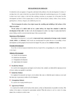
1 1 Approximate Lateral load Analysis by Portal Method Portal Frame Portal frames, used in several Civil Engineering structures like buildings, factories, bridges have the primary purpose of transferring horizontal loads applied at their tops to their foundations. Structural requirements usually necessitate the use of statically indeterminate layout for Portal frames, and Approximate solutions are often used in their analyses. (i) (ii) (iii) (iv) Portal Frame Structures Assumptions for the Approximate Solution In order to analyze a structure using the equations of statics only, the number of independent force components must be equal to the number of independent equations of statics. If there are n more independent force components in the structure than there are independent equations of statics, the structure is statically indeterminate to the nth degree. Therefore to obtain an Approximate solution of the structure based on statics only, it will be necessary to make n additional independent assumptions.
2 A solution based on statics will not be possible by making fewer than n assumptions, while more than n assumptions will not in general be consistent. Thus, the first step in the Approximate Analysis of structures is to find its degree of statical indeterminacy (dosi) and then to make appropriate number of assumptions. For example, the dosi of Portal frames shown in (i), (ii), (iii) and (iv) are 1, 3, 2 and 1 respectively. Based on the type of frame, the following assumptions can be made for Portal structures with a vertical axis of symmetry that are loaded horizontally at the top 1. The horizontal support reactions are equal 2. There is a point of inflection at the center of the unsupported height of each fixed based column Assumption 1 is used if dosi is an odd number ( , = 1 or 3) and Assumption 2 is used if dosi 1. Some additional assumptions can be made in order to solve the structure approximately for different loading and support conditions.
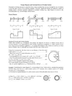
3 3. Horizontal body forces not applied at the top of a column can be divided into two forces ( , applied at the top and bottom of the column) based on simple supports 4. For hinged and fixed supports, the horizontal reactions for fixed supports can be assumed to be four times the horizontal reactions for hinged supports 2 Example Draw the axial force, shear force and bending moment diagrams of the frames loaded as shown below. (i) (ii) Solution (i) For this frame, dosi = 3 3 + 4 3 4 = 1; , Assumption 1 HA = HD = 10/2 = 5 k MA = 0 10 10 VD 15 = 0 VD = k Fy = 0 VA + VD = 0 VA = k Reactions AFD (k) SFD (k) BMD (k-ft) (ii) dosi = 3 3 + 6 3 4 = 3 Assumption 1 HA = HD = 10/2 = 5 k, Assumption 2 BME = BMF = 0 BMF = 0 HA 5 + MA = 0 MA = 25 k-ft; Similarly BME = 0 MD = 25 k-ft MA = 0 25 25 + 10 10 VD 15 = 0 VD = k Fy = 0 VA + VD = 0 VA = k Reactions AFD (k) SFD (k) BMD (k-ft) 5 25 k-ft k k 5 k 5 k E F D C B A 10 k 15 5 10 k 5 5 50 50 k k 5 k 5 k 10 k 5 5 5 25 25 25 k-ft 25 25 D C B A 10 k 15 10 3 (iii) dosi = 3 4 + 6 3 5 1 = 2; Assumption 1 and 2 BME = BMF = 0 BME = 0 (bottom) HA 5 + MA = 0 MA = 5HA.
4 Similarly BMF = 0 MD = 5HD Also BME = 0 (free body of EBCF) 10 5 VD 15 = 0 VD = k Fy = 0 VA + VD = 0 VA = VD = k BMG = 0 (between E and G) VA HA 5 = 0 HA = 5 k MA = 5HA = 25 k-ft Fx = 0 (entire structure) HA + HD + 10 = 0 5 + HD + 10 = 0 HD = 5 k MD = 5HD = 25 k-ft Reactions AFD (k) SFD (k) BMD (k-ft) (iv) dosi = 3 5 + 9 3 6 = 6 6 Assumptions needed to solve the structure Assumption 1 and 2 HA: HB: HC = 1: 2: 1 HA = 10/4 = k, HB = 5 k, HC = k MA = MC = 5 = k-ft, MB = 5 5 = 25 k-ft The other 4 assumptions are the assumed internal hinge locations at midpoints of columns and one beam Reactions BMD (k-ft) SFD (k) AFD (k) 10 k 10 k 25 k-ft MD VD HD G k-ft C B D C B A 10 k 10 k 10 F E YB YA 5 k k 25 k-ft F E 5 MA VA HA 25 k-ft k k 5 k 5 k 5 5 5 25 25 25 25 50 VA HA VD HD G k k-ft YC 25 25 5 4 Analysis of Multi-storied Structures by Portal Method Approximate methods of analyzing multi-storied structures are important because such structures are statically highly indeterminate.
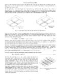
5 The number of assumptions that must be made to permit an Analysis by statics alone is equal to the degree of statical indeterminacy of the structure. Assumptions The assumptions used in the Approximate Analysis of Portal frames can be extended for the Lateral load Analysis of multi-storied structures. The Portal Method thus formulated is based on three assumptions 1. The shear force in an interior column is twice the shear force in an exterior column. 2. There is a point of inflection at the center of each column. 3. There is a point of inflection at the center of each beam. Assumption 1 is based on assuming the interior columns to be formed by columns of two adjacent bays or portals. Assumption 2 and 3 are based on observing the deflected shape of the structure. Example Use the Portal Method to draw the axial force, shear force and bending moment diagrams of the three-storied frame structure loaded as shown below. E A 40 40 40 15 15 15 3 3 15 10 15 18k 12k 6k 12 2@10=20 Beam BMD (k-ft) Beam SFD (k) Column AFD (k) 61 61 61 -3 -2 -2 -8 -2 1 2 -1 12 10 6 12 10 6 6 6 5 5 Column shear forces are at the ratio of 1:2:2:1.
6 Shear force in (V) columns IM, JN, KO, LP are [18 1/(1 + 2 + 2 + 1) =] 3k, [18 2/(1 + 2 + 2 + 1) =] 6k, 6k, 3k respectively. Similarly, VEI = 301/(6) = 5k, VFJ = 10k, VGK = 10k, VHL = 5k; and VAE = 361/(6) = 6k, VBF = 12k, VCG = 12k, VDH = 6k Bending moments are MIM = 310/2 = 15k, MJN = 30k, MKO = 30k, MLP = 15k MEI = 510/2 = 25k, MFJ = 50k, MGK = 50k, MHL = 25k MAE = 610/2 = 30k, MFJ = 60k, MGK = 60k, MHL = 30k M I F B N J G C O K H P L D The rest of the calculations follow from the free-body diagrams 72 50 30 25 15 36 25 15 36 72 50 30 Column SFD (k) Column BMD (k-ft) Beam AFD (k) -15 -9 -3 -10 -6 -2 -5 -3 -1 5 Problems on Lateral load Analysis by Portal Method 1. The figure below shows the shear forces (kips) in the interior columns of a two-storied frame. Use the Portal Method to calculate the corresponding (i) applied loads P1 and P2, (ii) column bending moments, (iii) beam axial forces. 2. The figure below shows the applied loads (F1, F2) and shear force (VEF) in column EF of a two-storied frame.
7 If F2 = 10 k, and VEF = 5 k, use the Portal Method to calculate the (i) applied load F1, (ii) maximum column bending moments. 3. For the structure shown in Question 2, use the Portal Method to calculate the Lateral loads F1, F2 if the axial forces in beams AD and BE are 10 kips and 15 kips respectively. 4. For the structure shown below, use the Portal Method to (i) draw the bending moment diagrams of the top floor beams AB and BC (i) calculate the applied load F1 if the maximum bending moment in column EH is 30 k-ft. 5. The figure below shows the exterior column shear forces (kips) in a four-storied fame. Calculate (i) the applied loads, (ii) beam shear forces. 5 3 20 20 12 10 P2 P1 F D E VEF 12 10 F1 F2 20 15 15 A C B I G H F D C B F1 F2 = 10 k 10 14 15 15 E A 4 @ 10 = 40 20 15 10 5 20 10 6 Analysis of Multi-storied Structures by Cantilever Method Although the results using the Portal Method are reasonable in most cases, the Method suffers due to the lack of consideration given to the variation of structural response due to the difference between sectional properties of various members.
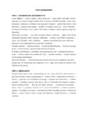
8 The Cantilever Method attempts to rectify this limitation by considering the cross-sectional areas of columns in distributing the axial forces in various columns of a story. Assumptions The Cantilever Method is based on three assumptions 1. The axial force in each column of a storey is proportional to its horizontal distance from the centroidal axis of all the columns of the storey. 2. There is a point of inflection at the center of each column. 3. There is a point of inflection at the center of each beam. Assumption 1 is based on assuming that the axial stresses can be obtained by a Method analogous to that used for determining the distribution of normal stresses on a transverse section of a cantilever beam. Assumption 2 and 3 are based on observing the deflected shape of the structure. Example Use the Cantilever Method to draw the axial force, shear force and bending moment diagrams of the three -storied frame structure loaded as shown below.
9 E A 15 5 5 15 18k 12k 6k 12 2@10=20 Beam BMD (k-ft) The dotted line is the column centerline (at all floors) Column axial forces are at the ratio of 20: 5: 5: 20. Axial force in (P) columns IM, JN, KO, LP are [18 5 20/{202 + 52 + (5)2 + (20)2} = ] , [18 5 5/(202 + 52 + (5)2 + (20)2} = ] , , respectively. Similarly, PEI = 33020/(850) = , PFJ = , PGK = , PHL = ; and PAE = 69620/(850) = , PBF = , PCG = , PDH = M I F B N J G C O K H P L D The rest of the calculations follow from the free-body diagrams Beam AFD (k) Beam SFD (k) Column AFD (k) Column BMD (k-ft) Column SFD (k) 7 Results from Exact Structural Analysis E A 15 10 15 18k 12k 6k 12 2@10=20 Beam BMD (k-ft) M I F B N J G C O K H P L D All members have equal cross-sections Beam AFD (k) Beam SFD (k) Column AFD (k) Column BMD (k-ft) Column SFD (k))
10 Beam BMD (k-ft) Beam AFD (k) Beam SFD (k) Column AFD (k) Column BMD (k-ft) Column SFD (k) Interior columns have twice the area of exterior columns 8 Problems on Lateral load Analysis by Cantilever Method 1. The figure below shows the axial forces (kips) in the exterior columns of a two-storied frame. If the cross-sectional area of column ABC is twice the area of the other columns, use the Cantilever Method to calculate the corresponding applied loads P1 and P2. 2. For the structure shown below, use the Cantilever Method to calculate the Lateral loads F1, F2 if the shear forces in beams AB and DE are 10 kips and 15 kips respectively. Assume all the columns have the same cross-sectional area. 3. Use the Cantilever Method to draw the axial force, shear force and bending moment diagrams of the three-storied structure loaded as shown below.