Transcription of AR-15 Lower Receiver Completion Guide Drill Jig
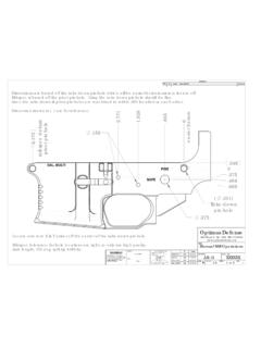
1 AR-15 Lower Receiver Completion Guide Drill Jig 2014 optimus Defense Rev. 0 Page: 1 Please carefully read these instructions in entirety before beginning. Overview: These instructions are meant to give you some direction in completing your optimus Defense 80% Lower Receiver . To complete the Lower you will be drilling multiple holes and routing two pockets. To keep the Lower Receiver within tolerance, take your time and pay close attention to the measurements as you machine. We offer recommended speeds, depths of cuts, and tool stick out lengths on the final page of this manual.
2 This Guide will cover using the optimus Defense Drill Jig to complete your Lower . Cutters: These tools are included in the optimus Defense Drill Jig: 3/8 End-mill with a 3/8 shank 1/4 End-mill with a 3/8 shank 3/8 Stub split tip Drill bit 5/32 Jobber split tip Drill bit 9/64 Jobber split tip Drill bit K ( ") Stub split tip Drill bit Other Tools: Drill Press and Vise C-Clamp (for securing vise to table) Safety Glasses Caliper and 6" ruler Cutting Fluid such as A-9 or Tap Magic Aluminum Manual Mill Drawings and Inspection Drawings (available at ) General Machining Practices: Use generous amounts of cutting fluid at all times, on the tool's cutting and rubbing surfaces.
3 Always peck Drill to prevent chips from packing into Drill flutes. At times it may be necessary to clamp the vice to the table to prevent excessive vibration. Procedure: Assemble the Drill jig 1. Using the two provided shoulder screws and one button head screw, assemble the Drill jig with the Lower sandwiched in between the two side plates. The shoulder screws go through the Lower 's take down and pivot pin holes, and the long button head cap screw goes through the magazine release hole. (See assembly drawing) Drilling the trigger pin, hammer pin, and selector holes 2. Lay the Drill jig on its right side and clamp in a vise. 3. Using the 5/32 Drill bit, Drill the hammer and trigger pin holes.
4 4. Using the 3/8 Drill bit, Drill the selector hole. Refer to Figure 2. Figure 1 Figure 2 AR-15 Lower Receiver Completion Guide Drill Jig 2014 optimus Defense Rev. 0 Page: 2 Fire Control Pocket 5. Stand the Drill jig upright and clamp it in the vise. Fasten the Fire Control Pocket Top Plate to the Drill jig in the "drilling position" (array of drilled holes closer to the buffer tube ear). Note: the top plate and the left side plate have circular notches that align. This is where you will set drilling depth and final routing dept.
5 6. Set the 9/64 Drill bit tool final depth using the exposed circular notch. See Figure 3. 7. Using the 9/64 Drill bit, Drill each of the 32 holes. 8. Remove the Fire Control Pocket Top Plate from the Drill jig. Load the 3/8 Drill bit and set the final drilling depth using the same circular notch as in step 6. 9. Using the 3/8 Drill bit, Drill the holes marked in Figure 4, effectively removing most of the material from the fire control pocket. Figure 5 shows most of the fire control pocket 3/8" drilled out. 10. Re-attach the Fire Control Pocket Top Plate with the routing pocket located over the fire control pocket area. See Figure 6. 11. Load the 3/8 end-mill and set the final tool depth using the same notch as in step 6.
6 12. Route out the fire control pocket using the top plate's routing pocket as a Guide . The first depth of cut must be + " below the top plate's top face, so that the flutes (cutting edges) of the end-mill does not cut in to the top plate. Move the cutter around the routing Guide in a clockwise direction (conventional milling direction). Warning: If the first depth ( ") is not set correctly, the Fire Control Pocket Top Plate will be damaged. 13. Route next depths about 1/4" to 3/8" deeper until final depth is reached. Figure 3 Figure 6 Figure 5 Figure 4 3/8" Drill the 14 holes shown in blue AR-15 Lower Receiver Completion Guide Drill Jig 2014 optimus Defense Rev.
7 0 Page: 3 Trigger Slot 14. Remove the Fire Control Pocket Top Plate and fasten the Trigger Slot Top Plate to the Drill jig in the "drilling position". Note: The top plate now aligns with a different circular slot for drilling and final routing depth. 15. Load the letter K (dia. ") Drill bit and set the final drilling depth using the exposed circular notch. Before turning the Drill press spindle ON, Lower the Drill bit through one of the holes until it is just above the floor of the fire control pocket. Then turn ON the Drill press spindle and Drill the hole. Repeat for all three holes through the floor of the fire control pocket.
8 Warning: If the K Drill bit flutes (cutting edges) touch the Trigger Slot Top Plate while the Drill is spinning, the Drill bit will "grab" and damage the top plate. 16. Rotate the Trigger Slot Top Plate so that the routing pocket is above the drilled holes. See Figure 8. 17. Load the 1/4" end-mill and set the final milling depth as before in Step 15. 18. Route out the trigger slot using the routing pocket as a Guide . Move the cutter around the pocket in a clockwise direction (conventional milling direction). Note: The Trigger Slot Top Plate routing pocket is design for a 1/4" end-mill with a 3/8" shank. 19. After machining both pockets take some measurements and compare it to the inspection drawing.
9 All dimensions should be within the tolerance noted on the drawing. If out of tolerance, carefully consider how it will affect the function of your Lower . De-burr 20. Using a suitable de-burr tool or sandpaper, carefully take down any sharp edges. Warning: Once you have machined any of the hammer, trigger and selector holes or the fire control pocket and trigger slot, you have what is considered to be a firearm. This firearm cannot be traded, gifted or sold without the assistance of a FFL. optimus Defense assumes no liability for the actions of the user of this product. You are responsible for knowing all laws and regulations in your area relating to this product. We are not lawyers, and this is not legal advice Figure 7 Figure 8 AR-15 Lower Receiver Completion Guide Drill Jig 2014 optimus Defense Rev.
10 0 Page: 4 Recommended Cutting Parameters: 3/8 End-mill Speed: 2050 RPM Stick Out: 2 First Depth of Cut: (below top plate's top) Next Depth of Cut: deeper or less 1/4 End-mill Speed: 3050 RPM Stick Out: 2 3/8 Drill Speed: 2000 RPM Stick Out: 2 Peck Drill : 5/32 Drill Speed: 4800 RPM Stick Out: 2 Peck Drill : 9/64 Drill Speed: 5450 RPM Stick Out: 2 Peck Drill : .070 K Drill (dia. ") Speed: 2700 RPM Stick Out: 2 Calculations: Definitions RPM Revolutions per Minute SFM Surface Feet per Minute Dia. Diameter of cutter Formulas RPM = SFM * / Dia. SFM for High Speed Steel cutting Aluminum is 200. (conservative cutting) Recommended RPMs are based off the above calculation.