Transcription of Article: TheGoodGainmethodforPI(D) controllertuning
1 Article: The Good Gain methodfor PI(D)controller tuningFinn HaugenTechTeach( )19. July 20101 IntroductionThe Good Gain method1is a simple, experimental method which can beused on a real process (without any knowledge about the process to becontrolled), or simulated system (in this case you need a mathematicalmodel of the process, of course), see Figure (ID)u0 AutoManualFigure 1:The Good Gain method for PID tuning is applied to the establishedcontrol Good Gain method aims at giving the control loop better stabilitythan what the famous Ziegler-Nichols methods the Closed-loop methodand the Open-loop method [3] gives.
2 The Ziegler-Nichols methods aredesigned to give an amplitude ratio between subsequent oscillations after astep change of the setpoin equal to 1/4 ( one-quarter decay ratio ). Thisis often regarded as poor stability. The Good Gain method gives betterstability. Furthermore, the Good Gain method does not require the control1 The method is developed by the to get into oscillations during the tuning, which is another benefitcompared with the Ziegler-Nichols Tuning procedureThe procedure described below assumes a PI controller, which is the mostcommonly used controller function.
3 However, a comment about how toinclude the D-term, so that the controller becomes a PID controller, is Bring the process to or close to the normal or specified operationpoint by adjusting the nominal control signalu0(with the controllerin manual mode).2. Ensure that the controller is a P controller withKp= 0(setTi= andTd= 0). IncreaseKpuntil the control loop gets good(satisfactory) stability as seen in the response in the measurementsignal after a step in the setpoint or in the disturbance(excitingwith a step in the disturbance may be impossible on a real system,but it is possible in a simulator).
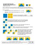
4 If you do not want to start withKp= 0, you can tryKp= 1(which is a good initial guess in manycases) and then increase or decrease theKpvalue until you observesome overshoot and a barely observable undershoot (or vice versa ifyou apply a setpoint step change the opposite way, a negativestep change), see Figure 2. This kind of response is assumed torepresent good stability of the control system. This gain value is important thatthe control signal is not driven to any saturationlimit(maximum or minimum value) during the experiment. If suchlimits are reached theKpvalue may not be a good one probablytoo large to provide good stability when the control system is innormal operation.
5 So, you should apply a relatively small stepchange of the setpoint ( 5% of the setpoint range), but not sosmall that the response drowns in Set the integral timeTiequal toTi= (1)whereTouis the time between the overshoot and the undershoot ofthe step response (a step in the setpoint) with the P controller, see2 Figure that for most systems (those which does not containta pure integrator) there will be offset from setpoint becausethecontroller during the tuning is just a P stepStep response in process measurementTou= Time between overshoot and undershootFigure 2:The Good Gain method: Reading off the time between the overshootand the undershoot of the step response with P controller4.
6 Because of the introduction of the I-term, the loop with the PIcontroller in action will probably have somewhat reduced stabilitythan with the P controller only. To compensate for this, theKpcanbe reduced somewhat, to 80% of the original value. Hence,Kp= (2)5. If you want to include the D-term, so that the controller becomes aPID controller3, you can try settingTdas follows:Td=Ti4(3)which is theTd Tirelation that was used by Ziegler and Nichols [3].2 Alternatively, you may apply a negative setpoint step, giving a similar response butdownwards.
7 In this caseTouis time between the undershoot and the remember the drawbacks about the D-term, namely that it amplifies the mea-surement noise, causing a more noisy controller signal thanwith a PI You should check the stability of the control system with the abovecontroller settings by applying a step change of the setpoint. If thestability is poor, try reducing the controller gain somewhat, possiblyin combination with increasing the integral 1PI controller tuning of a wood-chip level controlsystem with the Good Gain MethodI have tried the Ziegler-Nichols closed loop method on a level controlsystem for a wood-chip tank with feed screw and conveyor beltwhich runswith constant speed, see Figure 5 The purpose of the control system isto keep the chip level of the tank equal to the actual, measured level control system works as follows.
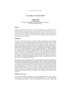
8 The controller tries to keep themeasured level equal to the level setpoint by adjusting the rotational speedof the feed screw as a function of the control error (which is the differencebetween the level setpoint and the measured level).During the tuning I foundKpGG= (4)andTou= 12min(5)The PI parameter values areKp= = (6)Ti= 12min= 18min= 1080s(7)Figure 4 shows the resulting responses with a setpoint step at time 20 minand a disturbance step (outflow step from 1500 to 1800 kg/min)at time120 min. The control system has good stability.
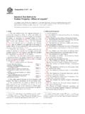
9 [End of Example 1]3 Theoretical backgroundIn the Good Gain method the process is controlled with a P-controller,and the step response in the process output due to a step in thesetpoint is4 This example is based on an existing system in the paper pulp factory S dra Cell Toftein Norway. The tank with conveyor belt is in the beginning of the paper pulp simulator of the system is available at [m]Wood chipWood chip tankud[kg/min]LTLCFeed screwProcess(tank with belt and screw)Sensor(LevelTransmitter- LT )ySPuePID controllerydBlock diagram:Process & Instrumentation (P &I) Diagram.
10 Level controllerSensor (Level transmitter)ControlvariableProcessoutput variableProcess disturbance(environmental variable)ControlerrorProcess measure-mentymProcessmeasure -mentymnMeasurement noiseReferenceorSetpointControlvariableP rocess output variableLevel controller (LC)ControlloopMeasure-mentfilterym,fFil teredmeasure-mentConveyor beltReferenceorSetpointySPMeasurement noisenProcess (tank with belt and screw)Process disturbance(environmental variable)Figure 3:P&I (Process and Instrumentation) diagram and block diagram of alevel control system for a wood-chip tank in a pulp factorywell-damped oscillations.