Transcription of Article Title: SPICE Models For Power Electronics
1 Article title : & quot ; SPICE Models For Power Electronics & quot ;Author: Meares andCharles E. HymowitzAbstract: Due to the increasing complexity of Power systems and the costs involvedin breadboarding and testing preliminary designs, engineers have been turning tocomputer based simulations for assistance in the design paper explains, in depth, how to create SPICE Models for the most importantand pervasive element in Power Electronics , that of the transformer and its accom-panying saturable :I Transformer ModelsII Saturable Reactor ModelIII How The Core model WorksIV Calculating Core ParametersV Using and Testing The CoreVI A Complete Transformer ModelVII ReferencesTotal: 11 Pages, 12 FiguresPage 2 Transformer ModelsThe usual method of simulating a transformer using ISSPICE is by specifying the opencircuit inductance seen at each winding and then adding the coupling coefficients toa pair of coupled inductors. This technique tends to loose the physical meaningassociated with leakage and magnetizing inductance and does not allow theinsertion of a nonlinear core.
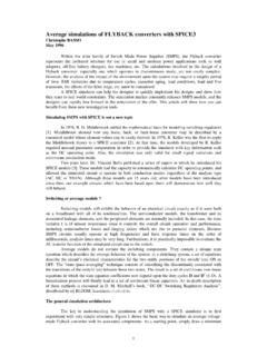
2 It does, however, provide a transformer that is simpleto create and simulates efficiently. The coupled inductor type of transformer, itsrelated equations and relationship to an ideal transformer with added leakage andmagnetizing inductance is shown in Figure order to make a transformer model that more closely represents the physicalprocesses, it is necessary to construct an ideal transformer and model the magne-tizing and leakage inductances separately. The ideal transformer is one thatpreserves the voltage and current relationships, shown in Figure 2, and has a unitycoupling coefficient and infinite magnetizing inductance. The ideal transformer,unlike a real transformer, will operate at DC. This property is useful for modeling theoperation of DC-DC = L1 di1 + M di2V2 = M di1 + L2 di2dt dtdt dtL1L2 LELMLEV1V21:NV2V1=KIf K 1L1 = LML2 = N2 L1K = 1 - LE/LMM = K L1 L2 Figure 1, The coupled inductor transformer, left, is computationally efficient, but itcannot provide access to LE and LM or be used as a building block.
3 The idealtransformer with discrete inductances and their relationship to the coupling coeffi-cient is shown on the For Power ElectronicsPage 3 The coupling coefficient of a transformer wound on a magnetic core is nearly unitywhen the core is not saturated and depends on the winding topology when the coreis saturated. The work of Hsu, Middlebrook and Cuk [3] develops the relationship ofleakage inductance, showing that relatively simple measurements of input induc-tance with shorted outputs yield the necessary model ISSPICE equivalent circuit for an ideal transformer is shown in Figure 3 andimplements the following equations:V1 RATIO = V2I1 = I2 RATIORP and RS are used to prevent singularities in applications where terminals 1 and2 are open circuited or terminals 3 and 4 are connected to a voltage source. RATIOis the turns ratio from winding 3,4 (secondary) to winding 1,2 (primary). Polarity dots are on terminals 1 and 3 as shown in Figure 2.
4 +V1-+ XFMR 1 2 3 4E 5 4 1 2 {RATIO}F 1 2 VM {RATIO}VM 5 6RP 1 2 1 MEGRS 6 3 3, The ISSPICE ideal transformer model allows operation at DC and theaddition of magnetizing and leakage inductances, as well as a saturable core tomake a complete transformer model . Parameter passing allows the transformerto simulate any turns 2, Symbol of an ideal transformer with the voltage to current = V1 N2 / N1I1 = I2 N2 / N1 Page 4 Multi-winding topologies can also be simulated by using combinations of this 2 that the ideal transformer has been constructed, magnetizing inductance canbe added using a separate saturable core model described Reactor ModelA saturable reactor is a magnetic circuit element consisting of a single coil woundaround a magnetic core. The presence of a magnetic core drastically alters thebehavior of the coil by increasing the magnetic flux and confining most of the flux tothe core.
5 The magnetic flux density, B, is a function of the applied MMF, which isproportional to ampere turns. The core consists of a number of tiny magneticdomains made up of magnetic dipoles. These domains set up a magnetic flux thatadds to or subtracts from the flux set up by the magnetizing current. After overcominginitial friction, the domains rotate like small DC motors, to become aligned with theapplied field. As the MMF is increased, the domains rotate one by one until they areall in alignment and the core saturates. Eddy currents are induced as the fluxchanges, causing added 4, Multiple winding transformers may be built out of combinations ofthe ideal transformer. RATIO equals V2/V1. The transformer is centertapped and V2 will equal SymbolActual TopologyISSPICE NetlistV2V3V1V2V3V1 ISSPICE Subcircuit CallX1 1 2 3 4 5 XFMR {RATIO=xxx }ISSPICE Subcircuit XFMR-TAP 1 2 3 4 5E1 7 8 1 2 {RATIO}F1 1 2 VM1 {RATIO}RP 1 2 1 MEGRS 6 3 1 UVM1 7 6F2 1 2 VM2 {RATIO}E2 9 5 1 2 {RATIO}R5 8 4 1 UVM2 9 5 The saturable reactor cannot be modeled using a single SPICE primitive , a saturable core macro model , utilizing the ISSPICE subcircuit feature,must be created.
6 The saturable core model is capable of simulating nonlineartransformer behavior including saturation, hysteresis, and eddy current losses. Tomake the model even more useful it has been parameterized. This is a techniquewhich allows the characteristics of the core to be determined just by the specificationof a few key parameters. At the time of the simulation, the specified parameters arepassed into the subcircuit. The equations in the subcircuit (inside the curly braces)are then evaluated and replaced with a value making the equation based subcircuitcompatible with any SPICE parameters that must be passed to the subcircuit include:Flux Capacity in Volt-Sec (VSEC)Initial Flux Capacity in Volt-Sec (IVSEC)Magnetizing Inductance in Henries (LMAG)Saturation Inductance in Henries (LSAT)Eddy current critical frequency in HZ (FEDDY).The saturable core may be added to the model of the ideal transformer to create amore complete transformer model .
7 To use the saturable core model just place thecore across the transformer's input terminals and evaluate the equations in curlybraces. A special subcircuit test point has been provided to allow the monitoring ofthe core flux. Since there are two connections in the subcircuit, no connection needbe made at the top subcircuit level other than the dummy node call to the saturable core subcircuit using ISSPICE would look like the following:X1 2 0 3 CORE {VSEC=50U IVSEC=-25U LMAG=10 MHY LSAT=20 UHY FEDDY=20 KHZ}Figure 5, To make the netlist for the saturable core subcircuit SPICE compatible, just replaceall the equations in the curly braces with numerical values. The key parameters are shown 5 6 {LSAT*500/VSEC}VP 7 2 250D1 6 7 DCLAMPVN 2 8 250D2 8 6 DCLAMP D(CJO={3*VSEC/+ ( *FEDDY*500*LMAG)} VJ=25). CORE 1 2 3F1 1 2 VM1 1G2 2 3 1 2 1E1 4 2 3 2 1VM1 4 5RX 3 2 1E12CB 3 2 {VSEC/500}+ IC={IVSEC/VSEC*500}RB 5 2 {LMAG*500/VSEC}Bottom (-)FluxTestPointTop (+)Page 6 How The Core model WorksModeling the physical process performed by a saturable core is most easilyaccomplished by developing an analog of the magnetic flux.
8 This is done byintegrating the voltage across the core and then shaping the flux analog withnonlinear elements to cause a current to flow proportional to the desired gives good results when there is no hysteresis as illustrated in Figure input voltage, V(2), is integrated using the voltage controlled current source, G,and the capacitor CB. An initial condition across the capacitor allows the core to havean initial flux. The output current from F is shaped as a function of flux using thevoltage sources VN and VP and diodes D1 and D2. The inductance in the highpermeability region is proportional to RB, while the inductance in the saturated regionis proportional to RS. Voltage VP and VN represent the saturation flux. Core lossesFigure 6, A simpleB-H loop modeldetailing somecore parametersthat will be usedfor later calcula-tions. mag,Lmag sat, LsatBHBmGECBFVMRBRSVPD1 VND2X1 COREV(3)FLUXFLUXINTEGRATIONV VS.
9 ISHAPING2 3 2 3 0 0 Figure 7, The novel saturable reactor subcircuit con-figuration. The symbol below the schematic displaysthe core's connectivity and flux test 7can be simulated by adding resistance across the input terminals; however, anotherequivalent method is to add capacitance across resistor RB in the in this capacitive element is differentiated in the model to produce the effectof resistance at the terminals. The capacitance can be made a nonlinear function ofvoltage which results in a loss term that is a function of flux. A simple but effectiveway of adding the nonlinear capacitance is to give the diode parameter, CJO, a value,as is done here. The other option is to use a nonlinear capacitor across nodes 2 and6, however, the capacitor's polynomial coefficients are a function of saturation flux,causing their recomputation if VP and VN are will increase linearly with frequency simulating high frequency core noticeable increase in MMF occurs when the core comes out of saturation, aneffect that is more pronounced for square wave excitation than for sinusoidalexcitation as shown in Figure 8.
10 These model properties agree closely with observedbehavior [2]. The model is set up for orthonol and steel core materials which havea sharp transition from the saturated to the unsaturated region. For permalloy coresthe transition out of saturation is less pronounced. To account for the differentresponse the capacitance value in the diode model (CJO in DCLAMP), which affectscore losses, should be scaled down. Also, scaling the voltage sources VN and VPdown will soften the DC B-H loop hysteresis, usually unnecessary for most applications, is notmodeled because of the extra model complexity, causing a prediction of lower lossat low frequencies. The hysteresis, however, does appear as a frequency dependentfunction, as seen on the previous page, providing reasonable results for mostapplications, including magnetic amplifiers. The model shown in Figure 7 simulatesthe core characteristics and takes into account the high frequency losses associatedwith eddy currents and transient widening of the B-H loop caused by magneticdomain angular momentum.