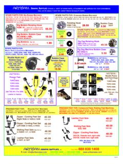
Transcription of artisan
1 artisan Hydraulic"Clicker". Cutting Machines Model No. A-922/925/928. A-922/925/928 1. Installation instruction manual Technical Specification Item A-922 A-925 A-928. Maximum Cutting Force Ton/kN 20/216 28/275 25/245. Cutting Table mm 900 430 1000x500 900 450. Usable Area Rate % 98 94 98. Rocker Width mm 370 370 500. Noise dB(A) 68-70 68-70 68-70. Rocker Speed: Starting 146 124. mm/s Cutting 51 45. Return 79 71. Motor Power HP/Kw 1 Weight (including oil) Kg 630 880 900. Weight (including pedestal) Kg 650 910 920. Weight (including seaworthy Kg 745 1000 1020. packing). Dynamic Overload Kg +75. Hydraulic Oil Kg ~25 ~38. Lifting and Placement When lifting this machine, it's required to use holes (see Fig. 1) of foundation and leather storage groove. It's not necessary to place the cutting machine on ground with a special device. If the ground is flat, it's enough to insert three damping parts (No. 01002013) into holes in the foundation. Preparation Each machine is supplied without a male plug.
2 Please install a plug applicable to onsite power supply at your own discretion. Before powering-on, please check if local voltage is the same as that recorded on tag of the machine. If wiring mode of the motor is be changed, for whatever reason, wiring mode of transformer must be changed accordingly to obtain required voltage value. Please Install the correct Twist-Lock Male Plug It's absolutely prohibited to connect the machine directly to the power supply. 1 . A-922/925/928 1. Installation instruction manual Installation of Machine with Full-load Hydraulic Oil Usually, each machine is filled with a proper amount of hydraulic oil before leaving the factory and the motor is wired according to the required voltage. When the rocker head moves up after starting the motor, the rotation direction of pump is correct. The rocker head will not raise up if the motor polarity is incorrect. Installation of Machine with No-load Hydraulic Oil If your machine was shipped without #46 hydraulic oil, because of transportation regulations, it's necessary to carefully fill up the oil tank from the notch at side of oil cylinder according to the following procedures: Fill up enough hydraulic oil until the oil reaches the position nearby the bottom of threaded hole under notch of to the maximum level.
3 Turn on the machine, observe if the pump rotates correctly according to the . above mentioned procedures. Rotate the rocker head counterclockwise until rocker head stops and then head should rise to maximum stroke. Place a block of wood at least 1" thick or other hard materials between the cutting table and head, start the machine. Push both switches on/off simultanously for several minutes. This procedure aims to remove air from relevant pipelines of oil cylinder. Remove previously used spacer, make sure there is nothing on cutting table, slowly rotate the adjustment disc clockwise until rocker goes down to a position that is about 3/8" away from the table surface. Then, check the oil amount in oil cylinder and refill with hydraulic oil as necessary. This way the necessary oil amount will be ensured in oil cylinder. Optional Parts This machine can be equipped with the following optional parts: Three-key Handle (No.: 03000928). Recommended Spare Parts To make the machine to be more complete, it's recommended to buy the following spare parts (by sequence of descending priority).
4 One circuit board (No.: 02E03947). One potentiometer (No.: 02001422). One coupling joint (No.: 01003628). One electromagnet (No.: 02001746). 2 . A-922/925/928. instruction manual 1. Installation One hose (No.: 02003636). One gear pump (with 60 Hz motor No.: 02003638). One oil filter (No.: 01000133).. And the following consumable parts: One cutting plate (A-918 No.: 02001185). (A-1018 No.: 02001186). One aluminum plate of rocker (A-918 No.: 01011453). (A1018 No.: 01001587). Eight screws (No.: 02000585). Eight washers (No.: 02000338). Eight nuts (No.: 02000121). Two switches of handle (No.: 02E03927). Rubber cap (No.: 02E03986). Pressure regulator (No.: 02001683). Pressure regulator (No.: 02001682). Coupling with elastic spider (No.: 02003628). Filter (No.: 01000133). Angle iron (No.: 01011455). Rubber sleeve(No.: 01011463). Spare Parts Note: To ensure good performance of machine, it's required to use A-series original spare parts directly from artisan , San Francisco, CA Spare parts can be delivered on condition that the following information is available: a) quantity of required spare parts.
5 B) identification number (listed on the following part drawings) of spare parts;. c) model number of machine;. d) serial number of machine;. For example: 2 pcs, No.: 02003634, model number of cutting machine: A-918, serial number: 3 . A-922/925/928. instruction manual 2. Usage Operation of Control Device Control devices can be pressed only after power supply is switched on! a) Adjustment disc on the right of rocker head is used to adjust stroke of rocker head. Rotate clockwise as shown in Fig. 3 and head descends; rotate to opposite direction and rocker ascends. Danger of Leaving Objects on Table Surface Whenever rotating the adjustment disc, make there is no other objects between the table surface and rocker head. b) The Rocker head rotates to left and right with a range of 180 degree. There is a single-key handle respectively at left side and right side. Operation Instruction of Three-key Handle (Special Order) Depending on Model A small keyboard may be installed on left handle.
6 The three keys No. 1, 2, and 3. are used to select the cutting head depth of travel. Pressing the correct key allows the operator to adjust cutting pressure when using different dies and leathers. When using fine cutting press knife to cut soft materials, choose No. 1 key (grey) on left of small keyboard for a prolong cutting time gradually through pressure divider shown in Fig. 5 until reaching proper cutting force. When using medium cutting press knife to cut semi-hard materials, choose No. 2 key (blue) on right of small keyboard. When using rough cutting press knife to cut materials that are especially hard to cut, choose No. 3 key (red) of small keyboard or increase its measured value gradually through pressure divider until reaching required cutting force.. 4 . A-922/925/928. instruction manual 2. Usage Cutting This machine has automatic stroke limitation function. Operators may use cutting dies with different heights without any adjustment, so operation procedure can be simplified as follows: Lay your leather or other materials on the cutting table, then place your die in the correct place.
7 After properly adjusting the stroke (recommended stroke:1/4" to 3/8") with adjustment disc, adjust the potentiometer to the proper cutting force and then simultaneously press the operation buttons on left and right handles. Release after the parts are cut and head begins to ascend back to the home position. Operation Instruction of Three-key Handle (Special Order). After adjusting the stroke (recommended stroke:1/4-3/8") with adjustment disc, simultaneously press the button on right handle and the most suitable of the three keys on left handle. According sharpness of cutting die, adjust the pressure divider working with #1 and #3 keys when necessary (see ). In this way, optimum cutting effect can be achieved and damage to the cutting table can be minimized. Note: Make sure the swing arm head fully covers your cutting die before pressing the operation buttons. (Fig. 6). Danger of Leaving Other Objects on Table Surface When Shutting Down Machine. About forty seconds after powering off the machine, the rocker head will begins to descend slowly.
8 (Fig. 7). DO NOT LEAVE or PLACE ANYTHING UNDER THE ROCKER HEAD. AFTER SHUTTING DOWN THE MACHINE! 5 . A-922/925/928. instruction manual 2. Usage Special Cutting Special cutting is used with small or thinner wall cutting dies. Usage: 1) Dial selection switch shown in the diagram to the position of special cutting ( ). If only two single-key handles are installed on the machine: 2) Reset potentiometer, placing the die and adjust the regulating handle of rocker head to determine proper height of rocker head. 3) Keep the height of rocker head unchanged and gradually adjust potentiometer until reaching required cutting effect. If three-key handle is installed on the machine: 4) Reset two potentiometers, place the die and adjust the regulating handle of rocker head to determine proper height of rocker head. 5) Keep height of rocker head unchanged and gradually adjust potentiometer of #1 key until #1 key reaches the required cutting effect. Keep the height of rocker head unchanged, put a cutting die with different wall heigth and gradually adjust the potentiometer of key #3 until the #3 key reaches required cutting effect.
9 6) When changing the height of rocker head or the size of cutting die, it's necessary to readjust the potentiometer to obtain the required cutting effect. 7) Turn the dial selection switch to standard cutting position and the machine will automatically position at stroke terminus. In other words, in mode of standard cutting , after the height of rocker head is changed, the pressure of the machine will stay unchanged. It is unnecessary to readjust potentiometer. Remarks: 8) Under standard configuration of our Clicker machines, the cutting dies used for cutting must be at least 5/8" in wall heights 9) DO NOT OPERATE YOUR MACHINE without block of wood or cutting die less than 1/2" under the cutting head. Damage to the machine WILL result! 10) Normal cutting is available only when the distance or total thickness of aluminum plate, work to be cut and cutting die between rocker head and table is above 2 inches. 6 . A-922/925/928 3. Maintenance and Upkeep instruction manual Regular Maintenance To ensure maximum performance of your quality artisan Clicker, We highly recommend you to do the following maintenance program: a) Turn over the cutting Pad (Fig.
10 2 of Part Diagram, No.: 02001185) every week. When your cutting pad is used up and no longer flat, it is necessary to have the cutting pad machined back to level or replaced. b) Turn over the aluminum alloy pressure plate ( of Part Diagram, No.: 01011453). attached to underside of the rocker head at least monthly. When no longer serviceable, have the plate machined flat or replace the plate. c) Daily, clean the collar ( of Part Diagram, # 01010413) used to seal off lubricant and remove all of the dust left after cutting. d) Replace the hydraulic oil and relevant filters after operating for the machine, 8000 hours, ( of Part Diagram, No.: 01000133);. e) Hydraulic oil must feature the following chemical and physical properties: ISO46, viscosity under 50 : Engler degree. For example: - Shell Tellus 46;. - ESSO Nuto H 46;. - TOTAL Azolla 46;. - AGIP Oso 46. Possible Problems and Solutions 1) Problem: inconsistent cutting effects are obtained from two consecutive strokes Check if the reostat ( of Part Diagram, #02003639) and hydraulic oil dispenser ( of Part Diagram, No.