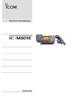
Transcription of INSTRUCTION MANUAL - Icom
1 INSTRUCTION MANUAL . HF/VHF/UHF. ALL MODE TRANSCEIVER. i7000. IMPORTANT EXPLICITDEFINITIONS. R E A D T H I S I N S T RU C T I O N M A N UA L WORD DEFINITION. CAREFULLY before attempting to operate the Personal death, serious injury or an transceiver. R DANGER! explosion may occur. Personal injur y, fire hazard or SAVE THIS INSTRUCTION MANUAL . This R WARNING! electric shock may occur. MANUAL contains important safety and operating instructions for the IC-7000. CAUTION Equipment damage may occur. Recommended for optimum use.
2 No NOTE risk of personal injury, fire or electric shock. FOREWORD SUPPLIED ACCESSORIES. We understand that you have a choice of many The transceiver comes with the following accesso- different radios in the market place. We want to take ries. a couple of moments of your time to thank you for Qty. making the IC-7000 your radio of choice, and hope q Hand microphone (HM-151) .. 1. you agree with Icom's philosophy of technology first. w DC power cable* (OPC-1457) .. 1. Many hours of research and development went into or (OPC-1457R).
3 1. the design of your IC-7000. e Spare fuse (ATC 5 A) .. 1. r Spare fuse (ATC 30 A) .. 2. D FEATURES t ACC 1. y (d) mm 1. IF DSP features u (d) mm Electronic keyer 1. All mode capability covering 160 2 m and i Microphone 1. 70 cm (depending on version) o Ferrite bead**.. 1. * Depending on the version. Compact with detachable front panel **Not supplied with the non-European versions. ppm of high frequency stability q e r Baudot RTTY demodulator Simple band scope function t S electable SSB transmission passband width (For both higher and lower pass frequency) y u i Standard voice synthesizer/voice recorder w For European versions Spurious signals may be received near the following frequencies.
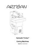
4 These are created in the internal circuit and w o does not indicate a transceiver malfunction: MHz, MHz (see page 19 for installation details). Icom, Icom Inc. and the Icom logo are registered trademarks of Icom Incorporated (Japan) in Japan, the United States, the United Kingdom, Germany, France, Spain, Russia and/or other countries. OPEN. THIS PAGE. i-1. ILLUSTRATIONS. Front panel !6. @4 @3 @2 @1 @0 !9 !8 !7. q w e !5. t yu i o !0 !1 !2 !4. !3. r HM-151. 3. z SPCH. /LOCK. TUNER. /CALL. XFC 2. 1. x V/M MW.
5 0. c F-1 F-2 . v , Mic element 7. 1 2 3 MODE. m 10 14 18 FIL. b 4 5 6. n 21 24 28 GENE. 7 8 9. 50 144 430.. 0 CE. F-INP. ENT. The front panel and HM-151's panel descriptions are described on pages 1. to 4, and on page 9, respectively (see the Chapter 1 PANEL DESCRIPTION'. for more details). i-2. Front panel Microphone (HM-151). q AF GAIN CONTROL [AF] (inner control; p. 33) z SPCH/LOCK KEY [SPCH/LOCK] (p. 34, 37). w RF GAIN CONTROL/SQUELCH CONTROL [RF/ x PTT SWITCH [PTT] (p. 37). SQL] (outer control; p.)
6 35). c UP/DOWN SWITCHES [Y]/[Z]. e POWER KEY [PWR] (p. 25). v TRANSMIT INDICATOR (p. 37). r FRONT PANEL LATCH (p. 16). b KEYPAD (pp. 28, 29). t PASSBAND TUNING/M-ch/RIT CONTROLS. [PBT/M-ch/RIT] (pp. 73, 77, 86, 100, 104) n FILTER SELECTION [FIL] (p. 75). y TWIN PBT (M-ch/RIT) INDICATOR m MODE KEY [MODE] (p. 34). (pp. 73, 77, 86, 100). , POWER INDICATOR. u MENU/GROUP KEYS [MENU/GRP] (p. 151) . PROGRAMMABLE FUNCTION KEYS [F-1]/[F-2]. i TUNER/CALL KEY [TUNER/CALL] 0 MEMORY WRITE [MW] (pp. 101, 102). (pp.
7 100, 114). 1 VFO/MEMORY SELECTION [V/M]. o MULTI-FUNCTION KEYS [F1]/[F2]/[F3]/[F4] (pp. 27, 100, 107). (pp. 5 8, 151). 2 TRANSMIT FREQUENCY CHECK [XFC]. !0 MANUAL NOTCH KEY [MNF/ADJ] (p. 81) (pp. 65, 89). !1 AUTO NOTCH/VOICE RECORDER KEY 3 TUNER/CALL KEY [TUNER/CALL]. [ANF/ REC] (pp. 80, 93) (pp. 100, 114). !2 SPCH/LOCK KEY [SPCH/LOCK] (pp. 34, 37). !3 MICROPHONE CONNECTOR (p. 10). !4 UP/DOWN (BAND) KEYS [p(band)]/[q(band)]. !5 MAIN DIAL TENSION LATCH. !6 HEADPHONE JACK [PHONES] (p. 18). !7 MAIN DIAL [DIAL].
8 !8 RECEIVE/TRANSMIT INDICATORS [RX]/[TX]. !9 TUNING STEP KEY [TS] (pp. 30 32). @0 NOISE BLANKER KEY [NB/ADJ] (p. 78). @1 NOISE REDUCTION KEY [NR/LEV] (p. 79). @2 FUNCTION DISPLAY (p. 13). @3 PRE AMP/ATTENUATOR KEY [ ]. (p. 72). @4 MODE KEY [MODE] (p. 34). i-3. PRECAUTIONS. R DANGER HIGH VOLTAGE! NEVER touch an an- Place the transceiver in a secure place to avoid inadvertent use tenna or internal antenna connector during transmission. by children. This may result in an electrical shock or burn. During mobile operation, NEVER place the transceiver R WARNING RF EXPOSURE!
9 This device emits Radio where air bag deployment may be obstructed. Frequency (RF) energy. Extreme caution should be ob- During mobile operation, DO NOT place the transceiver served when operating this device. If you have any questions where hot or cold air blows directly onto it. regarding RF exposure and safety standards please refer During mobile operation, DO NOT operate the transceiver to the Federal Communications Commission Office of Engi- without running the vehicle's engine. When the transceiver's neering and Technology's report on Evaluating Compliance power is ON and your vehicle's engine is OFF, the vehicle's with FCC Guidelines for Human Radio Frequency Electro- battery will soon become exhausted.
10 Magnetic Fields (OET Bulletin 65). Make sure the transceiver power is OFF before starting the R WARNING! NEVER operate the transceiver while driv- vehicle engine. This will avoid possible damage to the trans- ing a vehicle. Safe driving requires your full attention any- ceiver by ignition voltage spikes. thing less may result in an accident. During maritime mobile operation, keep the transceiver and R WARNING! NEVER operate the transceiver with an microphone as far away as possible from the magnetic navi- earphone, headphones or other audio accessories at high gation compass to prevent erroneous indications.