Transcription of Arty™ FPGA Board Reference Manual - Digilent Reference
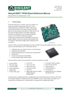
1 1300 Henley Court Pullman, WA 99163 Arty FPGA Board Reference Manual Revised June 7, 2017 This Manual applies to the Arty Rev. C DOC#: 510-319 Copyright Digilent , Inc. All rights reserved. Other product and company names mentioned may be trademarks of their respective owners. Page 1 of 18 Overview Arty is a ready-to-use development platform designed around the Artix-7 Field Programmable Gate Array (FPGA) from Xilinx. It was designed specifically for use as a MicroBlaze Soft Processing System. When used in this context, Arty becomes the most flexible processing platform you could hope to add to your collection, capable of adapting to whatever your project requires. Unlike other Single Board Computers, Arty isn t bound to a single set of processing peripherals: One moment it s a powerhouse chock-full of UARTS, SPIs, IICs, and an Ethernet MAC, and the next it s a meticulous timekeeper with a dozen 32-bit timers. The Arty Board .
2 Xilinx Artix-35T FPGA (xc7a35ticsg324-1L) o 33,280 logic cells in 5200 slices (each slice contains four 6-input LUTs and 8 flip-flops); o 1,800 Kbits of fast block RAM; o Five clock management tiles, each with a phase-locked loop (PLL); o 90 DSP slices; o Internal clock speeds exceeding 450 MHz; o On-chip analog-to-digital converter (XADC). o Programmable over JTAG and Quad-SPI Flash System Features o 256MB DDR3L with a 16-bit bus @ 667 MHz o 16MB Quad-SPI Flash o USB-JTAG Programming circuitry o Powered from USB or any 7V-15V source System Connectivity o 10/100 Mbps Ethernet o USB-UART Bridge Interaction and Sensory Devices o 4 Switches o 4 Buttons o 1 Reset Button o 4 LEDs o 4 RGB LEDs Expansion Connectors o 4 Pmod connectors o Arduino/chipKIT Shield connector Arty FPGA Board Reference Manual Copyright Digilent , Inc. All rights reserved. Other product and company names mentioned may be trademarks of their respective owners.
3 Page 2 of 18 Arty is fully compatible with the high-performance Vivado Design Suite. It is supported under the free WebPACK license, so designs can be implemented at no additional cost. This free license includes the ability to create MicroBlaze soft-core processor designs. Design resources, example projects, and tutorials are available for download at the Arty Resource Center, accessible from Table 1. Arty hardware callout descriptions. Callout Description Callout Description 1 FPGA programming DONE LED 11 SPI header (Arduino/chipKIT compatible) 2 Shared USB JTAG/UART port 12 chipKIT processor reset jumper 3 Ethernet connector 13 FPGA programming mode (JTAG/Flash) 4 Power select jumper (Ext. supply/USB) 14 chipKIT processor reset 5 Power jack (for optional ext. supply) 15 Pmod headers 6 Power good LED 16 FPGA programming reset button 7 User LEDs 17 SPI Flash 8 User slide switches 18 Artix FPGA 9 User push-buttons 19 Micron DDR3 memory 10 Arduino/chipKIT shield connectors 20 Analog devices ADP 5052 power supply Arty FPGA Board Reference Manual Copyright Digilent , Inc.
4 All rights reserved. Other product and company names mentioned may be trademarks of their respective owners. Page 3 of 18 2 Designing with Arty What makes Arty so flexible is its FPGA. Among their many features, FPGAs have the ability to transform into a custom software-defined System-on-a-Chip (SoC). These Soft SoC FPGA configurations are designed graphically using a tool called Vivado IP Integrator (Vivado IPI). In this tool, pre-built peripheral blocks are dragged from an extensive library and dropped into your processing system as you see fit. These pre-built peripherals include timers, UART/SPI/IIC controllers, and many of the other devices you would typically find in an SoC or microcontroller. Ambitious users will also find that they can create their own peripheral blocks by writing them in a Hardware Definition Language (HDL), specifically Verilog or vhdl . For those with no interest in learning HDL, the Xilinx High Level Synthesis tool can be used to define custom peripheral blocks by writing them in C.
5 Arty's Soft SoC configurations are powered by MicroBlaze processor cores. MicroBlaze is a 32-bit RISC soft processor core, designed specifically to be used in Xilinx FPGAs. The MicroBlaze processor in an Arty SoC configuration is typically run at 100 MHz, though it is possible to design your SoC so that it can operate at over 200 MHz. Arty supports large MicroBlaze programs with demanding memory requirements by providing 16MB of non-volatile program memory and 256MB of DDR3L RAM. Figure Vivado IPI. After you design your soft SoC configuration for Arty you can start writing programs for it. This is done by exporting your SoC design out of Vivado IPI and into the Xilinx Software Development Kit (XSDK), an Integrated Development Environment (IDE) for designing/debugging MicroBlaze programs in C. After the IPI to XSDK handoff, XSDK is automatically configured to include libraries and examples for the peripheral blocks you've included in your SoC.
6 At this point, programming the Arty is very similar to programming other SoC or microcontroller platforms: Programs are written in C, programmed into Board over USB, and then optionally debugged in hardware. Soft SoC configurations and MicroBlaze programs can also be loaded into the 16MB non-volatile program memory so that they execute immediately after Arty is powered on. Although the Arty is particularly well suited for MicroBlaze Soft SoC designs, it can also be programmed with a Register-Transfer Level (RTL) circuit description like any other FPGA development platform. This design flow requires that you describe your RTL circuit using an HDL within Vivado, and it does not use the Vivado IPI or XSDK tools. Designing this way has many advantages, but is very unlike programming a single Board computer, and Arty FPGA Board Reference Manual Copyright Digilent , Inc. All rights reserved. Other product and company names mentioned may be trademarks of their respective owners.
7 Page 4 of 18 instead is used by those familiar with FPGA design or interested in designing and implementing a digital circuit that doesn't contain a processor. Figure Xilinx Software Development Kit (XSDK). 3 Power Supplies The Arty Board requires a 5V power source to operate. This power source can come from the Digilent USB-JTAG port (J10) or it can be derived from a 7 to 15 Volt DC power supply that s connected to Power Jack (J12) or Pin 8 of Header J7. Header J13, located between the power jack and the Ethernet connector, is used to determine which source is used. A power-good LED (LD11), driven by the power good (PWRGD) output of the ADP5052 regulator, indicates that the Board is receiving power and that the onboard supplies are functioning as expected. An overview of the Arty power circuit is shown below. Figure Arty power circuit. Arty FPGA Board Reference Manual Copyright Digilent , Inc. All rights reserved. Other product and company names mentioned may be trademarks of their respective owners.
8 Page 5 of 18 The USB port can deliver enough power for the vast majority of designs. However, a few demanding applications, including any that drive multiple peripheral boards, might require more power than the USB port can provide. Also, some applications may need to run without being connected to a PC s USB port. In these instances, an external power supply or battery pack can be used. An external power supply can be used by plugging into Power Jack J12 and installing a jumper in the REG position on Header J13. The supply must use a coaxial, center-positive (or ) internal-diameter plug, and provide a voltage of 7 to 15 Volts DC. The supply should provide a minimum current of 1 amp. Ideally, the supply should be capable of providing 36 Watts of power (12 Volts DC, 3 amps). An external battery pack can be used by connecting the battery's positive terminal to pin 8 of J7 (labeled VIN) and the negative terminal to pin 7 of J7 (labeled GND), as shown in the figure below.
9 In order to use the battery pack as the Board s power source a jumper must be installed in the REG position on Header J13. The battery must provide a voltage between 7 and 15 volts DC, and should NOT be installed while there is a supply connected to Power Jack J12. Figure Battery pack connection. Voltage regulator circuits from Analog Devices and Texas Instruments create the required , , , , and supplies from the 5V power source. In the event that an external supply or battery pack is used, the on- Board Analog Devices 5V regulator provides the 5V source. The table below provides additional information (typical currents depend strongly on FPGA configuration and the values provided are typical of medium size/speed designs). Table 2. Voltage regulator circuit information. External Supply Voltage Monitoring The Arty Board includes circuitry for monitoring the voltage of an external supply connected to Power Jack J12, or an external battery pack connected to header J7.
10 A voltage divider is used to scale the unregulated input voltage, VU, to be within the range (0-1V) that the on-chip 12-bit ADC is capable of measuring. The unregulated input voltage, VU, is divided by 16 and then fed into Auxiliary Channel 2 on the XADC of the Artix 35T. Applications that Supply Circuits Device Current (max/typical) 5V On- Board regulators, RGB LEDs IC12: Analog Devices ADP2384 to 2A FPGA I/O, clocks, flash, Pmods, LEDs, buttons, switches, USB port, Ethernet IC11: Analog Devices ADP5052 FPGA Core and Block RAM IC11: Analog Devices ADP5052 to FPGA Auxiliary IC11: Analog Devices ADP5052 DDR3L and associated FPGA bank IC11: Analog Devices ADP5052 XADC analog Reference IC13: Texas Instruments REF3012 25mA/NA Arty FPGA Board Reference Manual Copyright Digilent , Inc. All rights reserved. Other product and company names mentioned may be trademarks of their respective owners. Page 6 of 18 wish to monitor the voltage of an external supply may configure Channel 2 of the XADC as a unipolar input and perform a conversion to receive a digital value corresponding to the input voltage.