Transcription of Assembly Solder Profile - Vishay
1 Assembly Solder Dale Revision: 13-Jun-121 Document Number: 34213 For technical questions, contact: DOCUMENT IS SUBJECT TO CHANGE WITHOUT NOTICE. THE PRODUCTS DESCRIBED HEREIN AND THIS DOCUMENTARE SUBJECT TO SPECIFIC DISCLAIMERS, SET FORTH AT InstructionsGENERALV ishay offers a wide product selection of inductors andtransformers in a variety of packages. This documentprovides instructions on mounting for the different types ofpackages, specifically on the different methods of soldering. If the device is to be mounted near heat-generatingcomponents, consideration must be given to the resultantincrease in ambient INSTRUCTIONSP rotection against overheating is essential when a device isbeing soldered.
2 Therefore, the connection wires or PCBtraces should be left as long as possible. The maximumpermissible soldering temperature is governed by themaximum permissible heat that may be applied to maximum soldering iron (or Solder bath) temperaturesare given in the individual Datasheets. During soldering, noforces must be transmitted from the pins to the case ( ,by spreading the pins).SOLDERING METHODST here are several methods for soldering devices onto thesubstrate. The following list is not complete.(a) Soldering in the Vapor PhaseSoldering in saturated vapor is also known as condensationsoldering.
3 This soldering process is used as a batch system(dual vapor system) or as a continuous single vapor systems may also include a pre-heating of theassemblies to prevent high temperature shock and otherundesired effects.(b) Infrared SolderingBy using infrared (IR) reflow soldering, the heating iscontact-free and the energy for heating the Assembly isderived from direct infrared radiation and from heating rate in an IR furnace depends on the absorptioncoefficients of the material surfaces and on the ratio ofcomponent's mass to an As-irradiated temperature of parts in an IR furnace, with a mixture ofradiation and convection, cannot be determined in measurement may be performed bymeasuring the temperature of a certain component while itis being transported through the temperatures of small components, soldered togetherwith larger ones.
4 May rise up to 280 parameters on the internal temperature of thecomponent are as follows: Time and power Mass of the component Size of the component Size of the printed circuit board Absorption coefficient of the surfaces Packing density Wavelength spectrum of the radiation source Ratio of radiated and convected energyAs a general rule of thumb, maximum temperature shouldbe reached within 360 s and time above Solder liquidstemperature should be reached in less than 180 s. Temperature/time profiles of the entire process and theinfluencing parameters are given. The IR reflow Profile isshown in Figure 1.
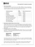
5 (c) Wave SolderingIn wave soldering one or more continuously replenishedwaves of molten Solder are generated, while the substratesto be soldered are moved in one direction across the crestof the wave. Maximum soldering temperature should notexceed 260 C for 20 s.(d) Iron SolderingThis process cannot be carried out in a controlled should therefore not be used in applications wherereliability is important. There is no SMD classification for thisprocess.(e) Laser SolderingThis is an excess heating soldering method. The energyabsorbed may heat the device to a much higher temperaturethan desired. There is no SMD classification for this processat the moment.
6 (f) Resistance SolderingThis is a soldering method which uses temperaturecontrolled tools (thermodes) for making Solder joints. Thereis no SMD classification for this process at the moment. Assembly Solder Dale Revision: 13-Jun-122 Document Number: 34213 For technical questions, contact: DOCUMENT IS SUBJECT TO CHANGE WITHOUT NOTICE. THE PRODUCTS DESCRIBED HEREIN AND THIS DOCUMENTARE SUBJECT TO SPECIFIC DISCLAIMERS, SET FORTH AT REFLOW SOLDERING Profile Fig. 1 - Infrared reflow soldering (SMD package)LEAD (Pb)-FREE Solder (SnAgCu) REFLOW Profile ATTRIBUTESPROFILE ATTRIBUTEPROFILE ATTRIBUTEPeak Reflow Temperature255 ( 5) CTime within 5 C of Peak Temperature30 s Temperature of Solder ~ 217 CCool Down Rate6 C/s above Liquidus60 s to 150 sPre-heat Temperature Range150 C to 200 CPre-heat Dwell Time60 s to 120 sMaximum Ramp Rate3 C/s Temperature of SolderPeak Reflow TemperatureTemperatureTimeDuration within 5 C of Peak Temp Time Above LiquidusRamp RatePre-Heat Dwell TimePre-Heat Temp RangeCool Down Rate