Transcription of August 2016 CONTINUOUSLY REINFORCED CONCRETE …
1 August 2016 . CONTINUOUSLY REINFORCED . CONCRETE pavement manual . Guidelines for Design, Construction, Maintenance, and Rehabilitation FHWA-HIF-16-026. Authors Jeffery R. Roesler, , University of Illinois at Urbana-Champaign Jacob E. Hiller, Michigan Technological University Alexander S. Brand, University of Illinois at Urbana-Champaign i ACKNOWLEDGEMENTS. This manual was produced for the Federal Highway Administration (FHWA) under a cooperative agreement with the CONCRETE Reinforcing Steel Institute (CRSI). The manual was reviewed and edited for publication by Samuel Tyson, , Federal Highway Administration, and Greg Halsted, , CONCRETE Reinforcing Steel Institute, with assistance from Shiraz Tayabji, , , Advanced CONCRETE Consultancy LLC. ii iii PREFACE. CONTINUOUSLY REINFORCED CONCRETE pavement (CRCP) was Today, CRCP is designed and constructed as a introduced in the United States almost 100 years ago when pavement of choice for long-life performance, the Bureau of Public Roads (now the Federal Highway recognizing that initial smoothness will be Administration) constructed a CRCP test section on maintained for decades and that maintenance Columbia Pike in Arlington, Virginia.
2 Since then, CRCP during that time will be minimal. This manual has been constructed in many states in the and in a provides guidance for materials selection and quality number of other countries. As experience with the design assurance, and for the mechanistic-empirical design, and construction of CRCP has grown, a variety of lessons construction, maintenance, and rehabilitation of learned through practical experience and research have CRCP. Case studies are summarized to document the contributed to the development of best practices for CRCP overall long-life performance of CRCP in the throughout its life cycle. and in other countries. iv TABLE OF CONTENTS. TABLE OF LIST OF LIST OF CHAPTER 1: INTRODUCTION AND What is CRCP?..2. When and Why is CRCP Used?..3. Overview of Key Points for CRCP Design CRCP manual Scope of the CRCP CHAPTER 2: CRCP DESIGN CRCP CRCP Performance Indicators and Distress Types ..10. CHAPTER 3: CRCP STRUCTURAL CRCP Design CRCP Main Design Inputs and Best Practices for Selecting CRCP AASHTO pavement ME Design Input Composite Pavements and Life Cycle Cost Analysis and Assessment of CHAPTER 4: REINFORCEMENT DESIGN AND Characteristics of Reinforcing Longitudinal Transverse CHAPTER 5: CRCP Reinforcement Construction Traffic Shoulders, Ramps, and Construction Techniques for Controlling Crack v CHAPTER 6: CRCP CRCP Experience in the International CRCP LTPP Program CHAPTER 7: CRCP RESTORATION AND Condition Overview of Maintenance and Repair Overlays on CHAPTER 8: USE OF CRCP AS AN Unbonded and Bonded CRCP Structural Design of CRCP CHAPTER 9: GUIDE SPECIFICATION FOR Guide APPENDIX A: APPENDIX B: vi LIST OF FIGURES.
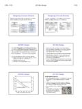
3 Figure 1. The three common CONCRETE pavement Figure 2. Newly constructed CRCP (Virginia)..3. Figure 3. Reinforcement design and placement is critical for good Figure 4. CONCRETE mixture design and materials are critical for good Figure 5. A typical CRCP Figure 6. Schematic of several factors influencing CRCP Figure 7. A typical CRCP punchout Figure 8. Schematic of CRCP punchout Figure 9. Spalling along transverse crack in a Figure 10. Horizontal cracking plane in Figure 11. Structural performance in terms of punchouts as a function of time or traffic Figure 12. Functional performance in terms of IRI as a function of time or traffic Figure 13. Framework of mechanistic-empirical design procedure for Figure 14. Impact of PCC thickness changes on predicted CRCP punchouts and terminal Figure 15. Impact of reinforcing steel percentage on predicted CRCP punchouts and terminal Figure 16. Impact of steel depth ( percent) on predicted CRCP punchouts and terminal Figure 17.
4 Impact of shoulder type on predicted CRCP punchouts and terminal Figure 18. Impact of base type and associated friction on predicted CRCP punchouts and terminal Figure 19. Impact of construction month on predicted CRCP punchouts and terminal Figure 20. Example of the ASTM marking requirements for a #11, Grade 60 bar (from CRSI)..34. Figure 21. Mill and coating certifications for reinforcing Figure 22. Steel placed on ATB (Virginia)..35. Figure 23. Two-layer steel reinforcement Figure 24. Lap Figure 25. Typical layout pattern for longitudinal steel with laps skewed across vii Figure 26. Typical lap-splice patterns (skewed and staggered) for longitudinal steel ..39. Figure 27. Planned location and tie bars for saw-cut longitudinal Figure 28. Longitudinal construction joint with tie Figure 29. Two-piece threaded tie bars for longitudinal construction Figure 30. Worker inspecting longitudinal reinforcing steel with transverse bars and chairs (Virginia).
5 45. Figure 31. Steel placed on chairs (Texas)..45. Figure 32. Two layers of steel placed on chairs (Texas)..45. Figure 33. Steel placed on transverse bar assemblies (Illinois)..46. Figure 34. Transverse bar assembly (TBA)..46. Figure 35. Placing longitudinal steel on Figure 36. Slip-form paving of CRCP (Illinois)..47. Figure 37. High-speed belt discharge of CONCRETE from end-dump truck (Virginia)..47. Figure 38. Application of curing compound on slip-formed Figure 39. Applying transverse tining on a new Figure 40. Transversely tined fresh CONCRETE on a new Figure 41. Longitudinal construction joint tied with two-piece tie Figure 42. Longitudinal (hinged) contraction Figure 43. Longitudinal free Figure 44. Wooden panels temporarily placed to facilitate removal of CONCRETE carried over end-of-day Figure 45. Finishing CONCRETE at end-of-day Figure 46. Transverse header joint with additional reinforcement in wheel Figure 47. Transition from CRCP using a sleeper slab and a wide-flange Figure 48.
6 Transition from CRCP using a modified wide Figure 49. Transition from CRCP using doweled Figure 50. Transition from CRCP using reduced longitudinal steel content with saw-cuts and doweled Figure 51. Transition between CRCP and asphalt pavement using a tapered CONCRETE viii Figure 52. Transition between CRCP and asphalt pavement using an elastomeric Figure 53. Seamless pavement for transitions of CRCP to and from Figure 54. CRCP block-out Figure 55. Layout of reinforcement in leave-out Figure 56. Recommended layouts for ramp Figure 57. Jointing details for ramp Figure 58. Design details for intersection of two CRCP alignments (Texas)..65. Figure 59. Longitudinal reinforcement lap splices and Figure 60. Lateral spacing of longitudinal Figure 61. Checking for position and movement of longitudinal Figure 62. Probing fresh CONCRETE to check the depth of longitudinal Figure 63. Construction of the 1947 Vandalia CRCP test sections (Illinois).
7 71. Figure 64. Construction of two-lift CRCP using two slip-form pavers on the A13 roadway (Belgium)..74. Figure 65. GFRP longitudinal reinforcement for CRCP (Canada)..75. Figure 66. Decision tree for assessing the need for restoration or Figure 67. Full-depth and partial-depth saw-cuts made in CRCP prior to CONCRETE removal ..85. Figure 68. New steel in FDR tied to longitudinal reinforcement protruding from Figure 69. Full-depth and partial-depth saw-cuts at boundaries of CRCP repair Figure 70. Longitudinal steel exposed in CRCP ready for splicing with new reinforcing Figure 71. New steel in FDR spliced to longitudinal steel exposed in Figure 72. Completed FDR in Figure 73. Tie bars drilled into existing CRCP for splicing with new reinforcement in FDR (Texas)..87. Figure 74. Jointed CONCRETE with dowels used for FDR of CRCP (South Carolina)..87. Figure 75. Cross-stitching a longitudinal Figure 76. Slot-stitching a longitudinal crack with tie bars to stabilize and provide load Figure 77.
8 Unbonded CRCP overlay under ix LIST OF TABLES. Table 1. Structural Adequacy of CRCP based on Number of Medium and High Severity Table 2. Allowable Steel Working Stress, ksi (MPa)..18. Table 3. Weight and Dimensions of ASTM Standard Reinforcing Steel Table 4. ASTM Standard Grades for Reinforcing Steel Table 5. Recommended Frictional Coefficients for CRCP Base Types by AASHTO pavement Table 6. Composite CRCP Exhibiting Good Table 7. Reinforcement Spacing Table 8. Maintenance and Repair Techniques for CRCP Structural and Functional Table 9. Example of Trigger and Limit Values for Diamond Table 10. Constructability, Performance, and Cost-Effectiveness of BCO, UBCOL, and AC Overlays of Table 11. Summary of Unbonded CRCP Overlays in x CHAPTER 1. INTRODUCTION AND OVERVIEW. 1. WHAT IS CRCP? CONTINUOUSLY REINFORCED CONCRETE pavement (CRCP). contains continuous, longitudinal steel reinforcement without transverse joints, except where required for end-of-day header joints, at bridge approaches, and at transitions to other pavement structures.
9 Continuous reinforcement is a strategy for managing the transverse cracking that occurs in all new CONCRETE pavements. In new CONCRETE pavements, volumetric changes caused by cement hydration, thermal effects, and external drying are restrained by the pavement base layer and longitudinal reinforcement causing tensile stresses to develop in the CONCRETE . These stresses, referred to as restraint stresses, increase more rapidly than the strength of the CONCRETE at early ages of the CONCRETE pavement , so, at some point, full-depth transverse cracks form, dividing the pavement into short, individual slabs. In CRCP, the continuous reinforcement results in internal restraint and produces transverse cracks that are closely spaced with small crack widths that help to maximize the aggregate interlock between adjacent CRCP panels. This feature is different from jointed plain CONCRETE pavements (JPCP), where the number and location of transverse cracks are typically managed by timely sawing.
10 In CRCP, the shorter panel sizes and high load transfer between adjacent CRCP panels reduce the flexural (bending) stresses from traffic loads and temperature and moisture curling. A. third type, jointed REINFORCED CONCRETE pavement (JRCP), incorporates wire mesh reinforcement equaling about percent of the cross-sectional area of the CONCRETE ;. however, it is no longer widely used for highway pavements in the The basic features of these three CONCRETE pavement types are shown in Figure 1. Figure 1. The three common CONCRETE pavement types. 2. WHEN AND WHY IS CRCP USED? CRCP can be expected to provide over 40 years of exceptional performance with minimal maintenance when CONTINUOUSLY REINFORCED CONCRETE is an excellent long-life properly designed and constructed. These attributes are pavement solution for highly-trafficked and heavily-loaded becoming increasingly important in high-traffic, heavy-truck roadways, such as interstate highways (Figure 2).