Transcription of AutoCAD Workbook 3D - hcmuaf.edu.vn
1 AutoCAD Workbook 3D 1 AutoCAD Workbook 3D DRA 54 Hartnell College Engineering Technology Parviz D. Entekhabi AutoCAD Workbook 3D 2 Lesson 01 Creating a Basic 3D Surface Model Elevation & Thickness To work in three dimensions in AutoCAD , we need to use a third axis on the rectangular (Cartesian coordinate system. This axis (defined as Z), determines the depth of an object. In this context, the X-axis will identify the WIDTH, the Y-axis LENGTH and the Z-axis determines the DEPTH of an object. 1. Start a new file from scratch. Accept all the default settings. 2. Turn the Grid and Snap ON (F7 & F9), and use the default spacing. Command: grid <Enter> Specify grid spacing(X) or [ON/OFF/Snap/Major/aDaptive/Limits/Follo w/Aspect] < >: L <Enter> Display grid beyond Limits [Yes/No] <Yes>: n <Enter> Command: <Enter> Specify grid spacing(X) or [ON/OFF/Snap/Major/aDaptive/Limits/Follo w/Aspect] < >: d <Enter> Turn adaptive behavior on [Yes/No] <Yes>: n <Enter> Command: <Enter> GRID Specify grid spacing(X) or [ON/OFF/Snap/Major/aDaptive/Limits/Follo w/Aspect] < >.)
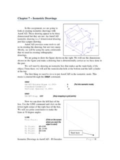
2 5 <Enter> {Press F7 to turn the grid ON} Command: <Grid on> Command: z <Enter> ZOOM Specify corner of window, enter a scale factor (nX or nXP), or [All/Center/Dynamic/Extents/Previous/Sca le/Window] <real time>: a <Enter> 3. Create a new layer named object, assign the color green to it, and make it the current layer. 1. AutoCAD Workbook 3D 3 4. Enter the ELEV Command and set the new default elevation at 1 and the new default thickness at 3 . Command: elev <Enter> Specify new default elevation < >: 1 <Enter> Specify new default thickness < >: 3 <Enter> 5. Begin you drawing with the LINE Command, and construct the figure 1.
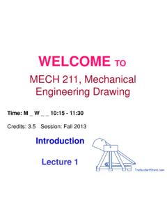
3 Do not be concern about the exact sizes. Keep your drawing proportional to one shown in Figure 1. 6. Use the VPOINT and set it to SE Isometric. Command: vpoint <Enter> Current view direction: VIEWDIR= , , Specify a view point or [Rotate] <display compass and tripod>: 1,-1,1 <Enter> Regenerating model. You may access this command from View pull down menu. (Figure 2) Figure 2 Your drawing in SE Isometric will look similar to one shown in figure 3. 7. Changing the Elevation and Thickness Command: elev <Enter> Specify new default elevation < >: -1 <Enter> Specify new default thickness < >: 6 <Enter> 1. AutoCAD Workbook 3D 4 Figure 1 PLAN VIEW Figure 3 3D View 8.
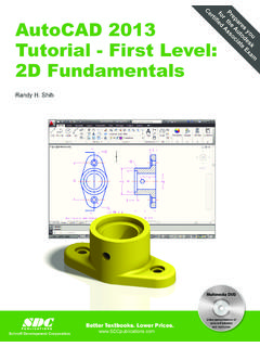
4 Add a circle as shown on Figure 4 and view from SE Isometric. (Figure 5) Figure 4 Figure 5 8. From the View Pull Down menu , select Hide , or enter the HIDE command from the keyboard. Fig. 6 1. AutoCAD Workbook 3D 5 Exercise 1-1 Construct a 3D solid model using Thickness and elevation change. (Figure 1-1) Figure 1-12. AutoCAD Workbook 3D 6 Lesson 02 Creating Primitives BOX Start a new file from scratch. Accept all the default settings. 1. Use the VPOINT and set it to SE Isometric. 2. Use the pull-down menu or the toolbar to select the desired command.
5 You may also type in command line. Command: vpoint <Enter> Current view direction: VIEWDIR= , , <Enter> Specify a view point or [Rotate] <display compass and tripod>: 1,-1,1 <Enter> Regenerating model. Command: box <Enter> Specify first corner or [Center]: {Pick a point anywhere on screen} Specify other corner or [Cube/Length]: L <Enter> Specify length: 4 <Enter> Specify width: 3 <Enter> Specify height or [2 Point]: 2 <Enter> 3. AutoCAD Workbook 3D 7 Lesson 03 Creating Primitives CYLINDER & WEDGE Command: cylinder <Enter> Specify center point of base or [3P/2P/Ttr/Elliptical]: {Pick a point anywhere on screen} Specify base radius or [Diameter]: 1 <Enter> Specify height or [2 Point/Axis endpoint] < >: 4 <Enter> Command: wedge <Enter> Specify first corner or [Center]: <Enter> Specify other corner or [Cube/Length]: L <Enter> Specify length < >: 3 <Enter> Specify width < >: 1 <Enter> Specify height or [2 Point] < >: 2 <Enter> 4.
6 AutoCAD Workbook 3D 8 Lesson 04 Creating Primitives CONE & FRUSTUM CONE Command: _cone <Enter> Specify center point of base or [3P/2P/Ttr/Elliptical]: 5,5 <Enter> Specify base radius or [Diameter] 2 <Enter> Specify height or [2 Point/Axis endpoint/Top radius] <0000>: _top Specify top radius 1 <Enter> Specify height or [2 Point/Axis endpoint] 3 <Enter> 5. AutoCAD Workbook 3D 9 Lesson 05 Creating Primitives PYRAMID Command: pyramid <Enter> 4 sides Circumscribed Specify center point of base or [Edge/Sides]: {Pick a point anywhere on screen} Specify base radius or [Inscribed] < >: 1 <Enter> Specify height or [2 Point/Axis endpoint/Top radius] < >: 3 <Enter> Command: pyramid <Enter> 4 sides Circumscribed Specify center point of base or [Edge/Sides]: S <Enter> {Pick a point anywhere on screen} Specify base radius or [Inscribed] < >.
7 2 <Enter> Specify height or [2 Point/Axis endpoint/Top radius] < >: 5 <Enter> Command: pyramid <Enter> 4 sides Circumscribed Specify center point of base or [Edge/Sides]: s <Enter> Enter number of sides <4>: 5 <Enter> Specify center point of base or [Edge/Sides]: Pick a point anywhere on screen} Specify base radius or [Inscribed]: <Enter> Specify height or [2 Point/Axis endpoint/Top radius] < >: t <Enter> Specify top radius < >: .5 <Enter> Specify height or [2 Point/Axis endpoint] < >: 6 <Enter> 6. AutoCAD Workbook 3D 10 Lesson 06 Creating Primitives SPHERE - TORUS Command: sphere <Enter> Specify center point or [3P/2P/Ttr]: {Pick a point anywhere on screen} Specify radius or [Diameter] < >: 2 <Enter> Command: torus Specify center point or [3P/2P/Ttr]: {Pick a point anywhere on screen} Specify radius or [Diameter] < >: 4 Specify tube radius or [2 Point/Diameter]: 1 Command: torus Specify center point or [3P/2P/Ttr]: {Pick a point anywhere on screen} Specify radius or [Diameter] < >: 4 Specify tube radius or [2 Point/Diameter] < >: 4 Command.
8 TORUS Specify center point or [3P/2P/Ttr]: {Pick a point anywhere on screen} Specify radius or [Diameter] < >: -1 Specify tube radius or [2 Point/Diameter] < >: 7. AutoCAD Workbook 2007 3D 11 Lesson 07 Creating Primitives POLYSOLID Command: polysolid <Enter> Specify start point or [Object/Height/Width/Justify] <Object>: w <Enter> Specify width < >: .4 <Enter> Specify start point or [Object/Height/Width/Justify] <Object>: h <Enter> Specify height < >: 3 <Enter> Specify start point or [Object/Height/Width/Justify] <Object>: {Pick a point anywhere on screen} Specify next point or [Arc/Undo]: <Ortho on> 3 <Enter> Specify next point or [Arc/Undo]: 2 <Enter> Specify next point or [Arc/Close/Undo]: 3 <Enter> Specify next point or [Arc/Close/Undo]: c (Figure A) Figure A Using the POLYLINE command (PL), to create the figure A.
9 Use POLYSOLID command; select Object option to construct Figure C . Grid space = Figure B Figure C 8. AutoCAD Workbook 3D 12 Lesson 08 Constructing a Planar Surface Command: _Planesurf <Enter> Specify first corner or [Object] <Object>: 4,4 <Enter> Specify other corner: 10,10 <Enter> (Fig. A) Command: l <Enter> LINE Specify first point: 11,11 <Enter> Specify next point or [Undo]: @10<90 <Enter> Specify next point or [Undo]: <Enter> (A) Command: o <Enter> OFFSET Current settings: Erase source=No Layer=Source OFFSETGAPTYPE=0 Specify offset distance or [Through/Erase/Layer] < >: 5 <Enter> Select object to offset or [Exit/Undo] <Exit>: {Select the line} Specify point on side to offset or [Exit/Multiple/Undo] <Exit>: {select the side} Use the ARC 3-point option to draw two arc as shown.
10 (Figure B) Figure A Figure B Command: _Planesurf <Enter> Specify first corner or [Object] <Object>: o <Enter> Select objects: {select line} 1 found Select objects: {select the line} 1 found, 2 total Select objects: {select the arc} 1 found, 3 total Select objects: {select the arc} 1 found, 4 total Select objects: <Enter> Figure C 8. AutoCAD Workbook 3D 13 Command: thicken <Enter> Select surfaces to thicken: {select the figure C}1 found Select surfaces to thicken: <Enter> Specify thickness < >: 2 <Enter> (Figure D) Figure D With the CONVTOSOLID command, you can convert the following objects into extruded 3D solids: Uniform-width wide polylines with thickness Closed, zero-width polylines with thickness Circles with thickness Note You cannot use CONVTOSOLID with polylines that contain vertices with 0 width or that contain segments of variable width.