Transcription of AV-30-C Installation Manual
1 AV-30-C . Installation Manual UAV-1003947-001. Rev E. 2020 - 2021 uAvionix Corporation. All rights reserved. uAvionix Corporation Bigfork, MT. Except as expressly provided herein, no part of this guide may be reproduced, transmitted, disseminated, downloaded, or stored in any storage medium, for any purpose without the express written permission of uAvionix. uAvionix grants permissions to download a single copy of this guide onto an electronic storage medium to be viewed for personal use, provided that the complete text of this copyright notice is retained. Unauthorized commercial distribution of this Manual or any revision hereto is strictly prohibited. uAvionix and Ping are registered trademarks of uAvionix Corporation and may not be used without express permission of uAvionix. AV-30, AV-30-E, and AV-30-C , BeaconX, tailBeaconX, and skyBeaconX are trademarks of uAvionix Corporation and may not be used without express permission of uAvionix.
2 Patents UAV-1003947-001, AV-30-C , Installation Manual 2. Rev E. 1 Revision History Revision Date Comments A 4/24/2020 Initial release Added Installation log-book entry requirement. Added method to determine proper screw length. Highlighted primary functions. Added B 7/13/2020. items included in the ICA. Added startup time and AoA reference per MOPS requirement. Added reference to CFR Added reference to AoA operation in inverted flight and operation in excess of G limits. C 8/10/2020. Added reference to utilize wire type in accordance with AC D 6/3/2021 Updated Top Level Assembly references. Software update to Added Definition of Acronyms & Terms section E 9/2/2021. Added requirement for pitot / static connection Add vibration check to System Checkout UAV-1003947-001, AV-30-C , Installation Manual 3. Rev E. 2 Warnings / Disclaimers All device operational procedures must be learned on the ground.
3 UAvionix is not liable for damages arising from the use or misuse of this product. This equipment is classified by the United States Department of Commerce's Bureau of Industry and Security (BIS) as Export Control Classification Number (ECCN) 7A994. These items are controlled by the Government and authorized for export only to the country of ultimate destination for use by the ultimate consignee or end-user(s) herein identified. They may not be resold, transferred, or otherwise disposed of, to any other country or to any person other than the authorized ultimate consignee or end-user(s), either in their original form or after being incorporated into other items, without first obtaining approval from the government or as otherwise authorized by law and regulations. UAV-1003947-001, AV-30-C , Installation Manual 4.
4 Rev E. 3 Limited Warranty uAvionix products are warranted to be free from defects in material and workmanship for two years from the Installation of AV-30-C on the aircraft. For the duration of the warranty period, uAvionix, at its sole option, will repair or replace any product which fails in normal use. Such repairs or replacement will be made at no charge to the customer for parts or labor, provided that the customer shall be responsible for any transportation cost. Restrictions: This warranty does not apply to cosmetic damage, consumable parts, damage caused by accident, abuse, misuse, fire or flood, theft, damage caused by unauthorized servicing, or product that has been modified or altered. Disclaimer of Warranty: IN NO EVENT, SHALL UAVIONIX BE LIABLE FOR. ANY INCIDENTAL, SPECIAL, INDIRECT OR CONSEQUENTIAL.
5 DAMAGES, WHETHER RESULTING FROM THE USE, MISUSE, OR. INABILITY TO USE THE PRODUCT OR FROM DEFECTS IN THE. PRODUCT. SOME STATES DO NOT ALLOW THE EXCLUSION OF. INCIDENTAL OR CONSEQUENTIAL DAMAGES, SO THE ABOVE. LIMITATIONS MAY NOT APPLY TO YOU. Warranty Service: Warranty repair service shall be provided directly by uAvionix. Proof of purchase for the product from uAvionix or authorized reseller is required to obtain and better expedite warranty service. Please email or call uAvionix support with a description of the problem you are experiencing. Also, please provide the model, serial number, shipping address and a daytime contact number. You will be promptly contacted with further troubleshooting steps or return instructions. It is recommended to use a shipping method with tracking and insurance. UAV-1003947-001, AV-30-C , Installation Manual 5.
6 Rev E. 4 Table of Contents 1 Revision History .. 3. 2 Warnings / Disclaimers .. 4. 3 Limited Warranty .. 5. 4 Table of Contents .. 6. 5 Introduction .. 8. Purpose .. 8. Definition of Acronyms & 8. 6 AV-30-C System Information .. 9. System Description .. 9. System Functions .. 11. 7 Certification .. 13. Mechanical Instrument Replacement .. 14. Non-Required Instrument Addition .. 14. Vacuum System 14. Applicable Performance Standards .. 15. 8 Installation Limitations .. 16. Installation Approval 16. 9 Installation Locations & Operating Modes .. 17. Installation Locations .. 17. Operating Mode Configuration .. 18. 10 Functionality and Required Interfaces .. 19. Aircraft Systems Connections .. 19. Feature Matrix .. 20. Power Input (Required) .. 21. Pitot and Static Interfaces (Required) .. 21. Outside Air Temp Input (Optional).
7 21. Audio Output (Optional) .. 22. GPS Interface (Optional) .. 22. Internal Magnetometer (Optional) .. 23. Internal Battery Operation .. 23. 11 Equipment Installation .. 24. Overview .. 24. Supplied Components .. 24. UAV-1003947-001, AV-30-C , Installation Manual 6. Rev E. Non-Supplied Components .. 25. Installation Records .. 25. Mechanical Drawing .. 26. Mounting Screw Length 27. Wiring Diagrams .. 28. Bonding Requirements .. 29. Unit Pinout .. 31. 12 Setup & Configuration .. 32. Startup and Common Controls .. 32. Available 33. 13 Installation Menu .. 34. Mandatory Settings .. 37. Unit Function .. 37. Function Lock .. 37. Trim .. 37. V-Speeds .. 37. Display Units .. 37. Serial Inputs .. 38. AID Mode .. 39. Demo Mode .. 40. System Checkout .. 40. Alignment .. 40. Gyro Calibration .. 41. OAT Interface .. 43. GPS Navigator Interface.
8 43. Vibration Check .. 44. EMC Checkout .. 46. 14 Troubleshooting .. 48. 15 Instructions for Continued Maintenance & Operation .. 49. 16 Aircraft Flight Manual 49. 17 Serial Interface Specification .. 50. 18 Field Update Capability .. 51. UAV-1003947-001, AV-30-C , Installation Manual 7. Rev E. 5 Introduction Purpose This Installation Manual applies to the following models: AV-30-C (Certified). Unless otherwise specified, all information in this document applies to all product variants. Definition of Acronyms & Terms Acronym Definition AI Attitude Indicator AoA Angle of Attack BARO Barometer; barometric DALT Density Altitude DG Directional Gyroscope GPS Global Positioning System HIRF High-Intensity Radiated Field IAS Indicated Airspeed MFD Multi-Function Display OAT Outside Air Temperature TAS True Airspeed TSO Technical Standard Order VMC Minimum controllable airspeed VYSE Best rate-of-climb speed with one engine inoperative Take-off safety speed.
9 The lowest speed at which the aircraft complies with V2. the handling criteria associated with the climb. VT Threshold crossing speed; target speed (after V2 has been reached). VSO Minimum stall speed with gear and full flaps. The bottom end of the ASI. white arc. VS1 Minimum steady flight velocity while still controllable. The bottom end of the ASI green arc. VFE Maximum flap extended velocity. The top end of the ASI white arc. VNO Maximum normal operating velocity. The top end of the ASI green arc. VNE Maximum velocity in smooth air (never exceed). The red line at the top end of the ASI yellow arc. VMC Minimum control airspeed with the critical engine inoperative VYSE Speed for best rate of climb OEI (single engine). UAV-1003947-001, AV-30-C , Installation Manual 8. Rev E. 6 AV-30-C System Information This document provides instructions on the Installation requirements for the uAvionix AV-30-C multi-mode instrument.
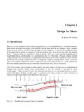
10 System Description The uAvionix AV-30-C is a fully digital multi-mode instrument that mounts in the legacy 3-1/8 round instrument panel. It can be field configured as either an Attitude Indicator (AI) or a Directional Gyro (DG) indicator. It is fully self- contained with dual-precision inertial and pressure sensors and allows for a wide variety of pilot customization. Figure 1 - AV-30-C Multi Mode AI/DG Basic Display When configured as an AI, primary attitude and slip are always displayed. The unused portions of the display area can be customized by the pilot to show a variety of textual and graphical data overlay fields. Three pages may be customized by the pilot while a fourth page presents a fully decluttered view of only attitude and slip. When configured as a Directional Gyro (DG), direction of flight information is presented.