Transcription of Basic Elements of Control Systems
1 UNESCO EOLSSSAMPLE CHAPTERSCONTROL Systems , ROBOTICS, AND AUTOMATION - Vol. I - Basic Elements of Control Systems - Ganti Prasada Rao Encyclopedia of Life Support Systems (EOLSS) Basic Elements OF Control Systems Ganti Prasada Rao International Centre for Water and Energy Systems , Abu Dhabi, UAE Keywords: Systems , Block diagram, Controller, Feedback, Open-loop Control , Closed-loop Control , Voltage Control system, Speed Control system, Position Control system, Liquid level Control , Temperature Control Contents 1. Dynamical Systems 2. Graphical Description of Systems 3. Open-loop Control and Closed-loop Control 4. Principal Functions of Control 5. The Basic Structure of Control Systems 6. Some Typical Examples of Control Voltage Control of a Generator Course Control of a Ship Liquid Level Control Control of a Heat Exchanger 7. A Brief Overview of the History of Control Systems Acknowledgements Glossary Bibliography Biographical Sketch Summary This article introduces the Basic concepts of negative feedback as applied to several simple Control Systems and presents some important aspects of graphical representation of Systems in block diagrams and signal flow graphs.
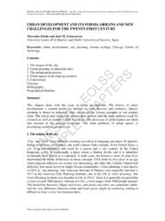
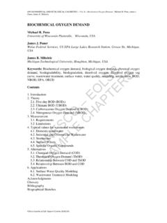
2 The developments in the field of automatic Control are briefly reviewed in the history of the field in four distinct periods. 1. Dynamical Systems A dynamical system manipulates entities such as energy, material, information, capital investment etc. It is characterized by relationships among certain variables that are chosen in its description. Usually inputs (causes) and outputs (effects) are important variables, which are connected by relations. Although a relationship is a function of time, the properties embedded in it may be time-invariant. A system may have only one input and one output. Such a system is termed a single-input-single-output (SISO) system. Some may be multiple-input-multiple-output (MIMO) Systems . Large Systems are characterized by several levels of organization, in a hierarchy. Figure 1 shows the schematic diagrams of Systems indicating such features. The fields of Systems , Control and information processing are closely related to the UNESCO EOLSSSAMPLE CHAPTERSCONTROL Systems , ROBOTICS, AND AUTOMATION - Vol.
3 I - Basic Elements of Control Systems - Ganti Prasada Rao Encyclopedia of Life Support Systems (EOLSS) science of cybernetics. Cybernetics attempts to understand the behavior of the system in nature. This understanding leads to the knowledge enabling us to improve the performance of natural or man-made processes. In recent years, techniques of Systems , Control and information processing, are handled with less reference to machines and other man-made physical processes, under the general name of Systems Science (see Systems Science and Cybernetics) Figure 1. Schematic representation of Systems UNESCO EOLSSSAMPLE CHAPTERSCONTROL Systems , ROBOTICS, AND AUTOMATION - Vol. I - Basic Elements of Control Systems - Ganti Prasada Rao Encyclopedia of Life Support Systems (EOLSS) 2. Graphical Description of Systems Dynamic Systems are denoted as transfer Elements . Every transfer element has at least one input and at least one output.
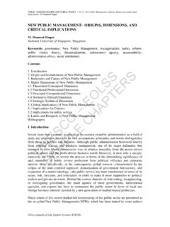
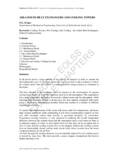
4 The transfer process in the element is denoted graphically in the form of a block diagram. The transfer Elements are shown as blocks connected to one another. Figure 2 shows an example. Table 1 shows certain symbols in a block diagram representation of Systems . Block diagrams are different from circuit diagrams or those showing effort and flow variables in that the output of a transfer element in a block diagram depends only on its own input but not on the Elements connected to its output side, in other words, there is no loading effect. Transfer Elements are also not reversible in their action, which is uniquely indicated by an arrow showing the direction of action. Figure 2. Example showing a system with several transfer Elements in the form of a block diagram. Table 1. Notation in block diagram representation of Systems . UNESCO EOLSSSAMPLE CHAPTERSCONTROL Systems , ROBOTICS, AND AUTOMATION - Vol. I - Basic Elements of Control Systems - Ganti Prasada Rao Encyclopedia of Life Support Systems (EOLSS) The transfer relation in an element can be represented in many forms in a block diagram.
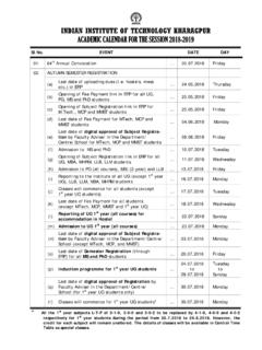
5 In the case of linear Systems , usually one inserts the related differential equation between the input and output or the transfer function or frequency response (see Description in Frequency Domain) in the related blocks as shown in Figures 3(a) and (b). Figure 3. Some possible descriptions of transfer Elements (a) Differential equation (b) Transfer function (c) Mathematical function (d) Graph of the input/output characteristic. In the case of static non-linear Elements , the description in the block symbol is either the mathematical functional description of the non-linear characteristic or the graph of the non-linear function as shown in Figures 3 (c) and (d). Variables in frequency domain are denoted by capital letters. Alternatively, signal flow graphs may also be used to describe Systems . Signal flow graphs are close in spirit to block diagrams. In a signal flow graph, the nodes represent signals and the branches between the nodes represent the transfer relations.
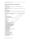
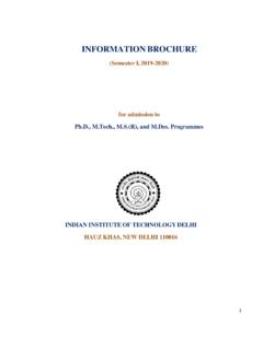
6 Figure 4 shows some examples of block diagrams and the corresponding signal flow graphs. UNESCO EOLSSSAMPLE CHAPTERSCONTROL Systems , ROBOTICS, AND AUTOMATION - Vol. I - Basic Elements of Control Systems - Ganti Prasada Rao Encyclopedia of Life Support Systems (EOLSS) Figure 4. Correspondence between signal flow graphs and block diagrams. 3. Open-loop Control and Closed-loop Control . The distinction between open-loop and closed-loop Control can be well understood with the help of the example of room temperature Control . In the open-loop Control scheme for room temperature shown in Figure 5, the ambient temperature A is measured and given to a controller, which controls the motor M, which in turn operates a valve V to Control the flow Q of the heating fluid in accordance with a relation Q = f(A ). The controller is preset to follow this relation. If the room temperature R changes, say due to an opening in the window, denoted as a disturbance z1, the valve V remains unaffected since only the ambient temperature influences the flows of warm fluid.
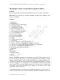
7 In this case, which is termed as open-loop Control , the effects of disturbances are not countered. Figure 5. Open-loop room temperature Control system UNESCO EOLSSSAMPLE CHAPTERSCONTROL Systems , ROBOTICS, AND AUTOMATION - Vol. I - Basic Elements of Control Systems - Ganti Prasada Rao Encyclopedia of Life Support Systems (EOLSS) Figure 6. Pre-determined Control strategies for three different settings. In the closed-loop Control scheme that is shown in Figure 7, the room temperature R is measured and compared with the desired or reference value w and the controller is driven by the disparity between R and w to alter the flow Q of the heating fluid. Figure 7. Closed-loop room temperature Control system. Unexpected changes may occur in R either due to the opening of the window or through sunlight entering the room, or both, but these are countered by the controller in closed-loop Control . The block diagrams of these two schemes, namely open-loop and closed-loop Control Systems , shown in Figures 8 and 9, make the difference between them clear.
8 Closed-loop Control is characterized by the following steps: Measurement of the controlled variable y or the actual value of the controlled plant output Determination of the Control error e = w y by comparison of the actual and the desired values of the controlled variable UNESCO EOLSSSAMPLE CHAPTERSCONTROL Systems , ROBOTICS, AND AUTOMATION - Vol. I - Basic Elements of Control Systems - Ganti Prasada Rao Encyclopedia of Life Support Systems (EOLSS) Use of the error to change u, the plant input, to reduce the Control error e to zero or to a negligible value. Figure 8. Block diagram of open-loop room temperature Control system. Figure 9. Block diagram of closed-loop room temperature Control system. Open-loop and closed-loop Control differ from each other in the following aspects: Close loop Control involves closed-loop operation or feedback, counters the effects of disturbances due to the action of negative feedback, and may be unstable, , the controlled variable (plant output) can either oscillate or grow beyond bounds.
9 Open-loop Control involves open-loop operation, can counter the effects of known disturbances only while other UNESCO EOLSSSAMPLE CHAPTERSCONTROL Systems , ROBOTICS, AND AUTOMATION - Vol. I - Basic Elements of Control Systems - Ganti Prasada Rao Encyclopedia of Life Support Systems (EOLSS) disturbances cannot be taken into account, and if the controlled object (plant) is itself stable, the Control system remains stable. - - - TO ACCESS ALL THE 21 PAGES OF THIS CHAPTER, Click here Bibliography Franklin , Powell , and Workman (1990). Digital Control of Dynamic Systems , 837pp., Addison-Wesley, Reading. [This is a widely used textbook that presents essential principles and design of digital Control Systems ]. Kuo (1987). Automatic Control Systems , , Englewood Cliffs. [This is a widely used textbook that presents essential principles and design of feedback Control Systems ]. Ogata K. (1990). Modern Control Engineering, 963pp.
10 Prentice-Hall, Englewood Cliffs. [A standard text presenting state space methods in Control ]. Biographical Sketch Ganti Prasada Rao was born in Seethanagaram, Andhra Pradesh, India, on August 25, 1942. He studied at the College of Engineering, Kakinada and received the degree in Electrical Engineering from Andhra University, Waltair, India in 1963, with first class and high honours. He received the ( Control Systems Engineering) and degrees in Electrical Engineering in 1965 and 1970 respectively, both from the Indian Institute of Technology (IIT), Kharagpur, India. From July 1969 to October 1971, he was with the Department of Electrical Engineering, PSG College of Technology, Coimbatore, India as an Assistant Professor. In October 1971, he joined the Department of Electrical Engineering, IIT Kharagpur as an Assistant Professor and was a Professor there from May 1978 to June 1997.