Transcription of Beacon 800 Gas Monitor Operator’s Manual
1 800 Gas MonitorOperator s ManualPart Number: 71-0037 RKRevision: GReleased: 7/27/18 Beacon 800 Gas Monitor operator s ManualProduct WarrantyRKI Instruments, Inc. warrants gas alarm equipment sold by us to be free from defects in materials, workmanship, and performance for a period of one year from date of shipment from RKI Instruments, Inc. Any parts found defective within that period will be repaired or replaced, at our option, free of charge. This warranty does not apply to those items, which by their nature, are subject to deterioration or consumption in normal service, and which must be cleaned, repaired, or replaced on a routine basis. Examples of such items are as follows:Warranty is voided by abuse including mechanical damage, alteration, rough handling, or repair procedures not in accordance with the operator s Manual .
2 This warranty indicates the full extent of our liability, and we are not responsible for removal or replacement costs, local repair costs, transportation costs, or contingent expenses incurred without our prior WARRANTY IS EXPRESSLY IN LIEU OF ANY AND ALL OTHER WARRANTIES AND REPRESENTATIONS, EXPRESSED OR IMPLIED, AND ALL OTHER OBLIGATIONS OR LIABILITIES ON THE PART OF RKI INSTRUMENTS, INC., INCLUDING BUT NOT LIMITED TO, THE WARRANTY OF MERCHANTABILITY OR FITNESS FOR A PARTICULAR PURPOSE. IN NO EVENT SHALL RKI INSTRUMENTS, INC. BE LIABLE FOR INDIRECT, INCIDENTAL, OR CONSEQUENTIAL LOSS OR DAMAGE OF ANY KIND CONNECTED WITH THE USE OF ITS PRODUCTS OR FAILURE OF ITS PRODUCTS TO FUNCTION OR OPERATE warranty covers instruments and parts sold to users by authorized distributors, dealers, and representatives as appointed by RKI Instruments, Inc.
3 We do not assume indemnification for any accident or damage caused by the operation of this gas Monitor , and our warranty is limited to the replacement of parts or our complete ) Absorbent cartridgesd) Batteriesb) Pump diaphragms and valvese) Filter elementsc) Fuses Beacon 800 Gas Monitor operator s ManualTable of ContentsChapter 1: Introduction .. 1 Overview .. 1 About the Beacon 800 Gas Monitor .. 1 About This Manual .. 1 Specifications .. 2 Chapter 2: Description .. 3 Overview .. 3 External Description .. 3 Internal Description .. 4 Chapter 3: Installation & Startup .. 9 Overview .. 9 Mounting the Beacon 800 Gas Monitor .. 9 Wiring the Beacon 800 Gas Monitor .. 12 Starting Up the Beacon 800 Gas Monitor .. 18 Chapter 4: Operation .. 19 Overview .. 19 Normal Operation .. 19 Alarm Indications.
4 20 Viewing & Resetting Min/Max Readings.. 24 Chapter 5: Configuration Menu .. 25 Overview .. 25 Enabling or Disabling Channels .. 26 Calibration Mode .. 27 Configure Channel Settings Menu .. 28 Chapter 6: Maintenance .. 31 Overview .. 31 Preventive Maintenance .. 31 Troubleshooting .. 31 Replacing the Fuses .. 33 Chapter 7: Optional Recorder Output Board & Heavy Duty Relay Board .. 34 Overview .. 34 Recorder Output Board .. 35 Heavy Duty Relay Board .. 38 Parts List .. 43 1 OverviewBeacon 800 Gas Monitor operator s ManualChapter 1: IntroductionOverviewThis chapter briefly describes the Beacon 800 Gas Monitor . This chapter also describes the Beacon 800 Gas Monitor operator s Manual (this document). Table 1 at the end of this chapter lists the specifications for the Beacon the Beacon 800 Gas MonitorThe Beacon 800 is a fixed-mounted, continuous-monitoring instrument.
5 This multiple channel gas Monitor is capable of detecting gas at up to eight locations. The display screens simultaneously display the gas readings of all active Beacon 800 includes audible and visual alarms that warn you of hazardous gas conditions. The alarm circuit includes two levels of gas alarms. The fail circuit alerts you to failures in the gas transmitter(s) or Beacon Configuration menu allows you to change channel and calibration this ManualThe Beacon 800 Gas Monitor operator s Manual is organized as follows: Chapter 1 is an introduction to the Beacon 800. Chapter 2 describes the components of the Beacon 800. Chapter 3 describes the installation and start-up procedures of the Beacon 800. Chapter 4 describes the operation of the Beacon 800. Chapter 5 describes the configuration procedures of the Beacon 800.
6 Chapter 6 describes the maintenance of the Beacon 800. Chapter 7 describes the optional Recorder Output and Heavy Duty Relay Beacon 800 Gas Monitor operator s Manual uses the following conventions for notes, cautions, and warnings:NOTE:Describes additional or critical :Describes potential damage to :Describes potential danger that can result in injury or death. Beacon 800 Gas Monitor operator s ManualSpecifications 2 SpecificationsTable 1 lists specifications for the Beacon 1: Beacon 800 SpecificationsDescriptionSpecificationIn put Power100 to 240 VAC or 24 VDCD etector Head Input Type2 or 3 wire 4-20mA transmittersConstruction (housing)Fiberglass/polyester with lexan window (NEMA 4X) in. H x in. W x in. D( cm H x cm W x cm D) lbs. (without AC line cord)Operating Temperature-4 F to 122 F (-20 C to 50 C)Storage Temperature-4 F to 158 F (-20 C to 70 C)RegulatoryCSA, NRTL/CEnvironmental Conditions For indoor or outdoor locations (Type 4X) 2000 meter max altitude Maximum humidity: 80% relative Pollution Degree 2 Installation Category IIUser Controls Reset switch Program buttons: ESCAPE, UP (YES), DOWN (NO), and ENTER)RelaysCSA Rated for 3 amps at 115 VAC resistive, Form C Standard AccessoryOperator s Manual (this document) 3 OverviewBeacon 800 Gas Monitor operator s ManualChapter 2: DescriptionOverviewThis chapter describes external and internal components of the Beacon 800 Gas DescriptionThis section describes the housing and all external components of the Beacon 800.
7 For the purposes of this description, the housing door is considered the front of the Beacon 800 s fiberglass housing is weather- and corrosion-resistant. It is suitable for installation where general purpose equipment is in use. The housing door is hinged on the left side and is secured by two latches on the right side. The display screens and status lights are visible through windows in the housing door. Four mounting feet are attached to the back of the housing (one at each corner). The mounting feet allow you to install the housing to a vertical surface. Four conduit hubs on the bottom of the housing are for external wiring :Only use the four factory installed conduit hubs on the bottom of the housing for wire entry into the housing. Do not drill the housing for any reason. CAUTION:To avoid electrical interference, do not route transmitter and power wiring through the same conduit SwitchThe reset switch is on the bottom of the housing, in front of the buzzer.
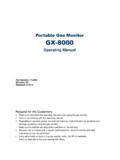
8 The reset switch serves three functions: Resets the alarm circuits for latched alarms after an alarm 1 or alarm 2 condition can set each channel for latched or self-resetting alarms in the channel setup pro-gram. See Chapter 5, Configuration, for more information. Silences the buzzer during an alarm 1 or alarm 2 condition. You cannot silence failure alarms. Displays and resets the minimum and maximum gas concentration buzzer is on the bottom of the housing, behind the reset switch. The buzzer sounds audible warnings to warn you of gas alarms and instrument failures. Beacon 800 Gas Monitor operator s ManualInternal Description 4 Internal DescriptionThis section describes the internal components of the Beacon 1: Beacon 800 Gas Monitor Component LocationDisplay ScreensNOTE:The display screens, status lights, and program buttons are mounted to a secondary circuit board.
9 This circuit board is mounted to the main circuit board by display screens simultaneously display the target gas, measuring unit, and current gas reading of all active channels. The top screen displays channels 1 through 4; the bottom screen displays channels 5 through display screens also display messages, settings, and other data when you are operating the configuration Terminal StripPower SwitchHousing (Shown without Door)Alarm 1 Terminal Strip (Channels 5 - 8)Ground StudPower SupplyReset SwitchAlarm 2 Terminal Strip(Channels 1 - 4)Display BoardMain BoardAlarm 2 Terminal Strip (Channels 5 - 8)Transmitter Terminal Strip(Channels 1 - 4)Buzzer (behind switch)Channel Relays (see F igure 3)Transmitter Terminal Strip(Channels 5 - 8)Conduit Hub (x4)Alarm 1 Terminal Strip(Channels 1 - 4)Controller Terminal Strip 5 Internal DescriptionBeacon 800 Gas Monitor operator s ManualFigure 2.
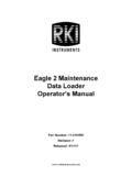
10 Display Board Component LocationStatus LightsThe Beacon 800 includes four status lights that indicate the current status of the Monitor : the ALARM 1 light, the ALARM 2 light, the FAIL light, and the PILOT light (see Figure 2).PILOT LightThe PILOT light is on when the Beacon 800 is receiving incoming power, either AC or DC LightThe FAIL light turns on when the Beacon 800 is experiencing a fail condition. A fail condition can be caused by a failure within the Beacon 800 or transmitter(s) wired to the Beacon 800 (see Chapter 6: Maintenance on page 31).ALARM 1 LightThe ALARM 1 light is on when the Beacon 800 is experiencing a low-level (alarm 1) orhigh-level (alarm 2) gas 2 LightThe ALARM 2 light is on when the Beacon 800 is experiencing a high-level (alarm 2) gas ButtonsThe Beacon 800 includes four program button that allow you to enter the Configuration Menu, navigate through the menu, update instrument and channel settings, and save changes to the settings.