Transcription of M2A Transmitter Operator’s Manual - RKI …
1 RKI Instruments, TransmitterOperator s Manual Part Number: 71-0305 RKRevision: HReleased: 12/3/18 M2A Transmitter operator s ManualWARNINGRead and understand this instruction Manual before operating instrument. Improper use of the gas monitor could result in bodily harm or calibration and maintenance of the gas monitor is essential for proper operation and correct readings. Please calibrate and maintain this instrument regularly! Frequency of calibration depends upon the type of use you have and the sensor types. Typical calibration frequencies for most applications are between 3 and 6 months, but can be required more often or less often based on your usage. M2A Transmitter operator s ManualProduct WarrantyRKI Instruments, Inc. warrants gas alarm equipment sold by us to be free from defects in materials, workmanship, and performance for a period of one year from date of shipment from RKI Instruments, Inc. Any parts found defective within that period will be repaired or replaced, at our option, free of charge.
2 This warranty does not apply to those items which by their nature are subject to deterioration or consumption in normal service, and which must be cleaned, repaired, or replaced on a routine basis. Examples of such items are:Warranty is voided by abuse including mechanical damage, alteration, rough handling, or repair procedures not in accordance with the operator s Manual . This warranty indicates the full extent of our liability, and we are not responsible for removal or replacement costs, local repair costs, transportation costs, or contingent expenses incurred without our prior WARRANTY IS EXPRESSLY IN LIEU OF ANY AND ALL OTHER WARRANTIES AND REPRESENTATIONS, EXPRESSED OR IMPLIED, AND ALL OTHER OBLIGATIONS OR LIABILITIES ON THE PART OF RKI INSTRUMENTS, INC. INCLUDING BUT NOT LIMITED TO, THE WARRANTY OF MERCHANTABILITY OR FITNESS FOR A PARTICULAR PURPOSE. IN NO EVENT SHALL RKI INSTRUMENTS, INC. BE LIABLE FOR INDIRECT, INCIDENTAL, OR CONSEQUENTIAL LOSS OR DAMAGE OF ANY KIND CONNECTED WITH THE USE OF ITS PRODUCTS OR FAILURE OF ITS PRODUCTS TO FUNCTION OR OPERATE warranty covers instruments and parts sold to users by authorized distributors, dealers, and representatives as appointed by RKI Instruments, do not assume indemnification for any accident or damage caused by the operation of this gas monitor, and our warranty is limited to the replacement of parts or our complete ) Absorbent cartridgesd) Batteriesb) Pump diaphragms and valvese) Filter elementsc) Fuses M2A Transmitter operator s ManualTable of ContentsChapter 1: Introduction.
3 6 Overview .. 6 About the M2A Transmitter .. 6 About this Manual .. 6 Specifications .. 7 Chapter 2: Description .. 9 Overview .. 9 External Description .. 9 Internal Description .. 17 Chapter 3: Installation & Startup .. 21 Overview .. 21 Mounting the M2A Transmitter .. 21 Wiring the M2A Transmitter .. 27 Start Up .. 33 Chapter 4: Operation .. 36 Overview .. 36 Normal Operation .. 36 Information Screen .. 364 - 20 mA Signal Output Operation .. 37 Alarm Indications .. 38 Chapter 5: Configuration Mode .. 41 Overview .. 41 Viewing & Changing M2A Parameters .. 41 Chapter 6: Gas Type Mode .. 44 Overview .. 44 Selecting the Gas Type .. 44 M2A Transmitter operator s ManualChapter 7: Maintenance .. 47 Overview.. 47 Preventive Maintenance .. 47 Troubleshooting .. 48 Calibration Frequency.. 50 Calibration, Combustible Gas, CO2, and Toxic Versions .. 51 Calibration, Oxygen Version .. 54 Replacing Components of the M2A .. 56 Chapter 8: RS-485 Modbus Output.
4 61 Overview.. 61 Wiring the M2A in a Modbus System .. 61 Using the M2A in a 4-wire Modbus System.. 64 Modbus Mode.. 64 Supported Modbus Functions.. 66 Parts List .. 70 Appendix A: Control Button Quick Reference Guide.. 75 Appendix B: PLC and DCS Device Wiring .. 76 Appendix C: Function Code 16 Registers.. 78(Appendix C available from RKI Instruments, Inc. Not included in Manual as normally provided with M2A detector head.) 6M2A Transmitter operator s ManualChapter 1: IntroductionOverviewThis chapter briefly describes the M2A Transmitter . This chapter also describes the M2A Transmitter operator s Manual (this document). Table 1 at the end of this chapter lists the specifications for the the M2A TransmitterThe M2A Transmitter is a fixed mount, continuous-monitoring detector head. All user adjustable parameters may be accessed using push button switches. In addition, calibration may be performed non-intrusively by use of a magnetic wand accessory which activates magnetic switches through a window at the front face of the detector M2A displays the current gas reading on an OLED display which is visible through the window in the cover (front face) and provides a 4 - 20 mA signal which indicates the target gas reading for use by a gas monitoring controller, recording device, or programmable controller.
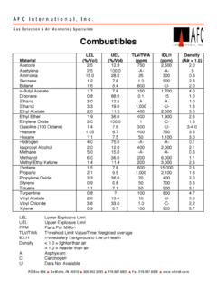
5 The M2A also provides an RS-485 Modbus output. Three sets of relay contacts, two controlled by the gas alarms and one by the fail alarm, rated at 115 VAC 5 amps are available for controlling devices such as lights or horns or for controlling higher rated operating modes allow you to display and change setup and calibration settings and change the gas type. They are Calibration Mode, Configuration Mode, Gas Type Mode, and Modbus this ManualThe M2A Transmitter operator s Manual uses the following conventions for notes, cautions, and :Describes additional or critical :Describes potential damage to :Describes potential danger that can result in injury or death. M2A Transmitter operator s Manual7 SpecificationsTable 1 lists specifications for the 1: M2A SpecificationsTarget Gas/Detection RangeCombustible Gas/Carbon Dioxide (CO2) Catalytic LEL: 0 - 100% LEL, 1% LEL increments (CH4 calibration unless otherwise specified. H2 specific detector available) Catalytic CH4 ppm: 0 - 9000 ppm, 20 ppm increments IR (infrared) CH4 LEL: 0 - 100% LEL, 1% LEL increments IR HC LEL: 0 - 100% LEL, 1% LEL increments (propane calibration) IR CH4 Volume: 0 - volume, increments IR CH4 Volume: 0 - 100 % volume, 1% increments IR CO2 ppm: 0 - 5,000 ppm, 20 ppm increments IR CO2 Volume: 0 - % volume, increments IR CO2 Volume: 0 - % volume, increments IR CO2 Volume: 0 - 100 % volume, 1% incrementsOxygen Oxygen (O2): 0 - % volume, incrementsCO/H2S Carbon Monoxide (CO): 0 - 300 ppm, 1 ppm increments Carbon Monoxide (CO): 0 - 200 ppm, 1 ppm increments Carbon Monoxide (CO): 0 - 100 ppm, 1 ppm increments Hydrogen Sulfide (H2S): 0 - 100 ppm, 1 ppm incrementsToxic Ammonia (NH3): 0 - ppm, ppm increments Arsine (AsH3): 0 - ppm, ppm increments Chlorine (Cl2): 0 - ppm, ppm increments Chlorine (Cl2).
6 0 - ppm, ppm increments Chlorine Dioxide (ClO2): 0 - ppm, ppm increments Hydrogen Cyanide (HCN): 0 - ppm, ppm increments Phosphine (PH3): 0 - ppm, ppm increments Sulphur Dioxide (SO2): 0 - ppm, ppm incrementsAlarm Settings(Alarm 1/Alarm 2)Ammonia: 12 ppm/25 ppmArsine: Dioxide 0 - 5,000 ppm: 2,500 ppm/5,000 ppmCarbon Dioxide 0 - : % %Carbon Dioxide 0 - : Dioxide 0 - 100%: 100%/100%Carbon Monoxide (all ranges): 25 ppm/50 ppmChlorine (0 - ppm): ppmChlorine (0 - ppm): ppmChlorine Dioxide (0 - ppm): ppmCombustible Gas (%LEL): 10 %LEL/50 %LELC ombustible Gas (0-100%Volume): 100 %/100 %Hydrogen Cyanide: ppmHydrogen Sulfide: 10 ppm/50 ppmMethane (ppm): 5000 ppm/8000 ppmMethane ( ): %Oxygen: (decreasing) (increasing)Phosphine: ppmSulphur Dioxide: ppm 8M2A Transmitter operator s ManualWARNING:When using the M2A, you must follow the instructions and warnings in this Manual to assure proper and safe operation of the M2A and to minimize the risk of personal injury.
7 Be sure to maintain and periodically calibrate the M2A as described in this (housing)Explosion-proof Junction Box, NEMA 4 XArea ClassificationExplosion-proof for Class I, Groups B, C, and D (Combustible, CO2, CSA Type CO and H2S, and CSA Type oxygen)Sampling MethodDiffusionInput Power 10 - 30 VDCC ontrols Three push button switches Three magnetic switches for non-intrusive Output 4 to 20 mA with impedance maximums listed below-12 VDC input: 500 ohms impedance max-24 VDC input: 1000 ohms impedance max RS-485 Modbus Explosion ProofNon-Explosion ProofOperating TemperatureCatalytic LEL/ppm-40 C to 75 CN/AOxygen-20 C to 45 C-20 C to 50 CH2S-40 C to 40 C-40 C to 50 CCO-5 C to 40 C-20 C to 50 CToxic (ESM-01)N/A-10 C to 40 CToxic (CT-7 Series)N/A-20 C to 40 CInfrared Combustible-20 C to 50 C-40 C to 50 CInfrared CO2-20 C to 50 C-40 C to 50 CAccuracyCatalytic Combustible Gas (LEL range): 5% of reading or 2% LEL (whichever is greater)Catalytic CH4 (ppm range): 5% of reading or 50 ppm (whichever is greater)**IR Combustible Gas/IR CO2: 5% of reading or 2% of full scale (whichever is greater)Oxygen: O2 Hydrogen Sulfide: 5% of reading or 2 ppm H2S (whichever is greater)Carbon Monoxide: 5% of reading or 5 ppm CO (whichever is greater)Toxic Sensors (ESM-01 Type and CT-7 Series Type): 10% of reading or 5% of full scale (whichever is greater)* These are RKI factory settings.
8 See Viewing & Changing M2A Parameters on page 41 to change the alarm settings. **Independent of zero 1: M2A Specifications M2A Transmitter operator s Manual9 Chapter 2: DescriptionOverviewThis chapter describes external and internal components of the M2A DescriptionThis section describes the junction box and all external components of the M2A Transmitter . Figure 1: M2A External ComponentsJunction BoxThe M2A s cast aluminum junction box is dust and weather resistant. The junction box also protects the M2A and all connections made to it. Use the three 3/4 NPT conduit ports to mount the detector to the junction box (factory installed in the bottom port) and connect wiring from an external device (left port). The top port is shipped with a factory installed and sealed conduit plug to avoid leaks into the junction box. If necessary, the conduit plug can be removed and the top port can be used for :If the top conduit port is used for wiring, be sure to seal the threads to ensure water does not enter the junction box.
9 See Wiring the M2A Transmitter on page 27 for complete wiring Box Cover3/4 N PT Conduit Port, Plugged3/4 N PTConduit PortWindowMounting Slot (2x)Detector(Catalytic LEL Detector S hown) 10M2A Transmitter operator s ManualUse the junction box s two mounting holes to mount the M2A to a vertical surface at the monitoring site. The window in the cover on the front of the junction box allows you to view the OLED display and use the magnetic wand to actuate the magnetic control switches so you can perform non-intrusive calibration. Removing the cover allows you to access the interior of the junction WandThe magnetic wand is a short plastic rod with a magnet in one end. It is used to actuate the magnetic control switches on the control PCB while the junction box cover is still installed so that non-intrusive calibration can be DetectorThe gas detector senses the target gas and is mounted in a 3/4 NPT conduit port on the right bottom side of the M2A. A variety of detectors may be used with the M2A.
10 See the sections below for descriptions of each type of DetectorsThe catalytic detectors have a 1/2 NPT thread and require a 3/4 NPT x 1/2 NPT reducer to install in the detector port. The table below outlines the M2A part numbers and replacement detector part numbers for the catalytic 2: Catalytic DetectorsFigure 2: Catalytic SensorsTarget Gas, RangeM2A Part NumberDetector UsedCombustible Gas, 0 - 100% LEL65-2640RK61-0140RK (Catalytic UL version)65-2640RK-0561-0140RK-05 (Catalytic CSA version)Hydrogen, 0 - 100% LEL65-2641 RKNC-6205-01 (Catalytic UL version, hydrogen specific)65-2641RK-05NC-6205-05 (Catalytic CSA version, hydrogen specific)Methane, 0 - 9000 ppm65-2647RK61-0140 RKA (Catalytic UL version)65-2647RK-0561-0140 RKA-05 (Catalytic CSA version)DetectorPartNumbers61-0140RK61-0 140 RKANC-6205-01 DetectorPartNumbers61-0140RK-0561-0140 RKA-05NC-6205-05 M2A Transmitter operator s Manual11 Infrared (IR) DetectorsThe IR combustible detectors are generally used instead of the catalytic combustible detectors in applications where there may be catalyst poisons such as silicone present or where oxygen is not present in the monitoring environment.