Transcription of BEAM-COLUMNS
1 BEAM-COLUMNS . SUMMARY: Structural members subjected to axial compression and bending are known as beam columns . The interaction of normal force and bending may be treated elastically or plastically using equilibrium for the classification of cross-section. The behaviour and design of BEAM-COLUMNS are presented within the context of members subjected to uniaxial bending , deformation takes place only in the plane of the applied moments. In the case of BEAM-COLUMNS which are susceptible to lateral-torsional buckling, the out-of-plane flexural buckling of the column has to be combined with the lateral-torsional buckling of the beam using the relevant interaction formulae. For BEAM-COLUMNS with biaxial bending , the interaction formula is expanded by an additional term.
2 OBJECTIVES: Evaluate the in-plane bending and axial compression force for BEAM-COLUMNS . Calculate the lateral-torsional buckling of BEAM-COLUMNS . Calculate the biaxial bending and axial compression force for BEAM-COLUMNS . REFERENCES: Eurocode 3: design of steel structures Part General rules and rules for buildings. Chen W F and Atsuta T: Theory of BEAM-COLUMNS Vols. 1 & 2, McGraw-Hill, 1976. Trahair N. & Bradford M: Behaviour and design of Steel Structures , 2nd edt., Chapman & Hall, 1988. Dowling P J, Owens G W & Knowles P: Structural Steel design , Butterworths, 1988. Nethercot D A: Limit State design of Structural Steelwork , 2nd edition, Chapman and Hall, 1991. CONTENTS: 1. Introduction. 2. In-plane behaviour of BEAM-COLUMNS .
3 Cross-sectional behaviour. Overall stability. Treatment in Eurocode 3. The role of ky. 3. Lateral-torsional behaviour of BEAM-COLUMNS . Lateral-torsional buckling. The design process in Eurocode 3. The role of kLT. 4. Biaxial bending of BEAM-COLUMNS . design for biaxial bending and compression. Cross-section checks. 5. Verification methods for isolated members and whole frames. 6. Concluding summary. 1. INTRODUCTION. BEAM-COLUMNS are defined as members subject to combined bending and compression. In principle, all members in frame structures are actually BEAM-COLUMNS , with the particular cases of beams (N = 0) and columns (M = 0) simply being the two extremes. Depending upon the exact way in which the applied loading is transferred into the member, the form of support provided and the member's cross-sectional shape, different forms of response will be possible.
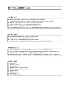
4 The simplest of these involves bending applied about one principal axis only, with the member responding by bending solely in the plane of the applied moment. 2. IN-PLANE BEHAVIOUR OF BEAM-COLUMNS . When a beam -column is subjected to in plane bending (figure 1a), its behaviour shows an interaction between beam bending and compression member buckling, as indicated in figure 1b. Figure 1 In-plane behaviour of BEAM-COLUMNS . Curve 1 shows the beam elastic linear behaviour. Curve 6 shows the limiting behaviour of a rigid-plastic beam at the full plastic moment Mpl. Curve 2 shows the transition of real elastic-plastic beams from curve 1 to curve 6. The elastic buckling load of a concentrically loaded compression member, Ncr is shown in curve 4.
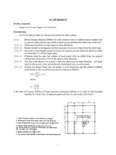
5 Curve 3 shows the interaction between bending and buckling in elastic members, and allows for the traditional moment N v exerted by the axial load. Curve 7 shows the interaction between bending moment and axial force causing the member to become fully plastic. This curve allows for the reduction from the full plastic moment Mpl to Mpr caused by the axial load, and for the additional moment Nv. The actual behaviour of a beam -column is shown by curve 5 which provides a transition from curve 3. for elastic members to curve 7 for full plasticity. CROSS-SECTIONAL BEHAVIOUR. bending and axial force for class 1 and 2 cross-sections. If full plasticity is allowed to occur, then the failure condition will be as shown in figure 2 and the combination of axial load and moment giving this condition will be: Figure 2 Full plasticity under axial load and moment.
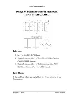
6 A. For yn (h t f ) / 2 neutral axis in web N M = 2 f y t w yn h 2t f . 2.. M N = f y bt f (h t f ) + f y yn2 t w (1). 2 . b. For y n > (h t f ) / 2 neutral axis in flange h . N M = f y t w (h 2t f ) + 2b t f + y n . 2 . h . M N = f y b y n (h y n )t f (2). 2 . Figure 3 compares Eqs. (1) and (2) with the approximation used in Eurocode 3 of: Eurocode 3. M Ny. Rd = M pl . y (1 n) /(1 0,5a) but M Ny. Rd M (3) ( ) or eq. in which n = N Sd / N pl .Rd is the ratio of axial load to squash load (fy A), and a = ( A 2bt f ) / A 0,5. For cross-sections without bolt holes, the following approximations may be used for z axis moments: for n > a : M Nz. Rd = M pl . z .Rd Eurocode 3. n a 2 ( ) or for n > a : M Nz . Rd = M pl . z .Rd 1 . 1 a.
7 Eq. and where n = N Sd / N pl .Rd and a = ( A 2bt f ) / A but a 0,5 . Figure 3 Full plasticity interaction major axis bending of HEA 450 section. Eurocode 3. Further simplifications for a range of common cross-sectional shapes are provided in Table 1. Table 1 Expressions for reduced plastic moment resistance MN (Notation: n = NSd / ). Cross-section Shape Expression for MN Rolled I or H M N , y = 1,11M pl . y (1 n) ( ). M N , z = 1,56 M (1 n)(0,6 + n) ( ). Square hollow section M N , y = 1,26 M pl (1 n) ( ). M N , y = 1,33M pl . y (1 n) ( ). Rectangular hollow section 1 n M N , y = M pl .z 0,5 +. ht ( ). A. Circular hollow M N , y = 1,04 M pl (1 n1,7 ) ( ). section In all cases the value of MN should, of course, not exceed that of Mpl.
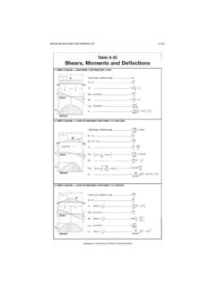
8 bending and axial force for Class 3 cross-sections. Figure 4 shows a point somewhere along the length of an H-shape column where the applied compression and moment about the y axis produce the uniform and varying stress distribution shown in figures 4a and 4b. Figure 4 Elastic behaviour of cross-section in compression and bending . For elastic behaviour the principle of superposition may be used to simply add the two stress distributions as shown in figure 4c. First yield will therefore develop at the edge where the maximum compressive bending stress occurs and will correspond to the condition: fy = c + b where: fy is the material yield stress, h is the overall depth of section and I is the second moment of area about the y axis.
9 C = N / A is the stress due to the compressive load N. Mh / 2. b = is the maximum compressive stress due to the moment M. I. Class 3 cross-sections will be satisfactory if the maximum longitudinal stress satisfies the criterion: Eurocode 3. f yd ; f yd = f y / M 0 ( ) or eq. bending and axial force for class 4 cross-sections. Class 4 cross-sections will be satisfactory if the maximum longitudinal stress calculated using the effective widths of the compression elements ( (2) of EC3) satisfies the criterion: Eurocode 3. f yd ; f yd = f y / M 0 ( ) or eq. OVERALL STABILITY. The treatment of cross-sectional behaviour in the previous section took no account of the exact way in which the moment M at the particular cross-section under consideration was generated.
10 Figure 5 shows a beam -column undergoing lateral deflection as a result of the combination of compression and equal and opposite moments applied at the ends. Figure 5 Primary and secondary moments. The moment at any point within the length may conveniently be regarded as being composed of: primary moment M. secondary moment N v. Using elastic strut theory gives the maximum deflection at the centre (Trahair & Bradford, 1988) as: M N. vmax = sec 1 (4). N 2 PEy 2 EI y where PEy = is the Euler critical load for major axis buckling, and the maximum moment is: L2. N. M max = M sec (5). 2 PEy In both equations the secant term may be replaced by noting that the first order deflection (due only to the end moments) and the first order moment (ordinary beam theory) are approximately amplified by: 1.