Search results with tag "Flexural members"

Design of Beams and Other Flexural Members per AISC LRFD ...
www.pdhonline.comthe design of beams and other flexural members. 3. Stability of Beam Sections As long as a beam remain stable up to the fully plastic condition as depicted on Figure 2, the nominal moment strength can be taken as the plastic moment capacity as given in Equations 4 and 5. Instability in beams subject to moment arises from the buckling tendency of
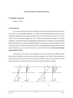
5. Flexural Analysis and Design of Beams 5.1. Reading ...
www.ce.memphis.eduFor nonprestressed flexural members and prestressed members with axial load less than 0.10f′ cA g the net tensile strain Á t at nominal strength shall not be less than 0.004. Ã max = 0.85β 1 f c′ f y Á u Á u +0.004
Design of Reinforced Concrete Beams per ACI 318-02
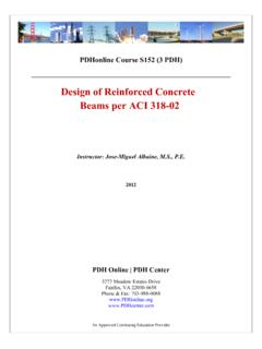
www.pdhonline.comcompression-controlled strain limit and 0.005 are considered as part of the transition strain limit zone (Fig. 7). Furthermore, for nonprestressed flexural members and nonprestressed members with axial load less than 0.10f’cAg, the net tensile strain εt is limited to 0.004 (section 10.3.5). This provision covers beams and slabs
Design of Beams (Flexural Members) (Part 5 of AISC/LRFD)
user.engineering.uiowa.eduLRFD Specifications (Part 16 of LRFD Manual) Basic Theory If the axial load effects are negligible, it is a beam; otherwise it is a beam-column. J.S Arora/Q. Wang 1 BeamDesign.doc . 53:134 Structural Design II Shapes that are built up from plate elements are usually called plate
Design of Beams (Flexural Members) (Part 5 of AISC/LRFD)
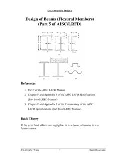
user.engineering.uiowa.edu53:134 Structural Design II My = the maximum moment that brings the beam to the point of yielding For plastic analysis, the bending stress everywhere in the section is Fy , the plastic moment is a F Z A M F p y ⎟ = y 2 Mp = plastic moment A = total cross-sectional area a = distance between the resultant tension and compression forces on the cross-section a A