Flexural Members
Found 9 free book(s)
Design of Beams and Other Flexural Members per AISC LRFD ...
www.pdhonline.comthe design of beams and other flexural members. 3. Stability of Beam Sections As long as a beam remain stable up to the fully plastic condition as depicted on Figure 2, the nominal moment strength can be taken as the plastic moment capacity as given in Equations 4 and 5. Instability in beams subject to moment arises from the buckling tendency of
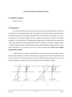
5. Flexural Analysis and Design of Beams 5.1. Reading ...
www.ce.memphis.eduFor nonprestressed flexural members and prestressed members with axial load less than 0.10f′ cA g the net tensile strain Á t at nominal strength shall not be less than 0.004. Ã max = 0.85β 1 f c′ f y Á u Á u +0.004
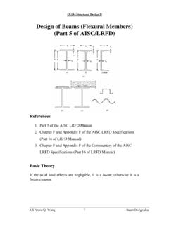
Design of Beams (Flexural Members) (Part 5 of AISC/LRFD)
user.engineering.uiowa.edu53:134 Structural Design II My = the maximum moment that brings the beam to the point of yielding For plastic analysis, the bending stress everywhere in the section is Fy , the plastic moment is a F Z A M F p y ⎟ = y 2 Mp = plastic moment A = total cross-sectional area a = distance between the resultant tension and compression forces on the cross-section a A
1.0 INTRODUCTION TO STRUCTURAL ENGINEERING 1.1 …
www.egr.msu.edu• All the members of a truss are connected using pin/hinge connections. All external forces are applied at the pins/hinges. As a result, all truss members are subjected to axial forces (tension or compression) only. • In braced and moment frames, the horizontal members (beams) are subjected to flexural loads only.
COMPANION TO THE AISC STEEL CONSTRUCTION MANUAL
www.aisc.orgTable 6-A. Available Strength for Members Subject to Axial, Shear, Flexural and Combined Forces—W-Shapes Table 6-A is the same as AISC Manual Table 6-2, except it provides the available strength for Fy = 65 ksi and Fu = 80 ksi (ASTM A913 Grade 65). Discussion on the use of this table can be found in Part 6 of the AISC Manual.
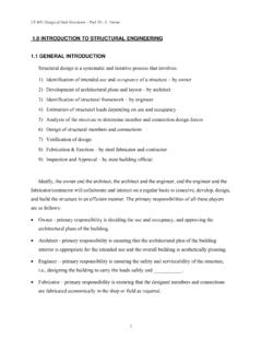
Curved Beams - courses.washington.edu
courses.washington.eduCURVED MEMBERS IN FLEXURE The distribution of stress in a curved flexural member is determined by using the following assumptions. 1 The cross section has an axis of symmetry in a plane along the length of the beam. 2 Plane cross sections remain plane after bending. 3 The modulus of elasticity is the same in tension as in compression.
BEAM-COLUMNS - UERJ
www.labciv.eng.uerj.brBEAM-COLUMNS SUMMARY: • Structural members subjected to axial compression and bending are known as beam columns. • The interaction of normal force and bending may be treated elastically or plastically using equilibrium for the classification of cross-section. • The behaviour and design of beam-columns are presented within the context of members subjected

IS 13920 (1993): Ductile detailing of reinforced concrete ...
law.resource.orgthe members and joints are capable of resisting forces primarily by flexure. 4 SYMBOLS For the purpose of this standard, the following letter symbols shall have the meaning indicated against each; where other symbols are used, they are explained at the appropriate place. All

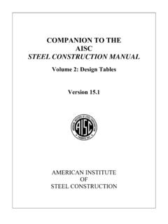
Chapter 2. Design of Beams – Flexure and Shear
www.egr.msu.eduCE 405: Design of Steel Structures – Prof. Dr. A. Varma Chapter 2. Design of Beams – Flexure and Shear 2.1 Section force-deformation response & Plastic Moment (Mp) • A beam is a structural member that is subjected primarily to transverse loads and negligible