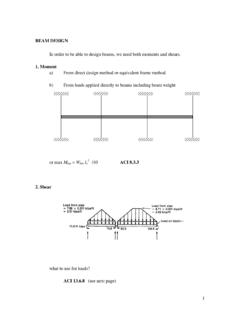
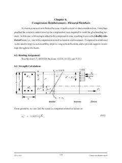
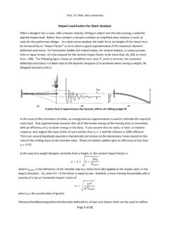
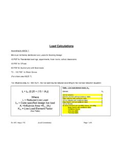
Transcription of Beam Stiffness - Memphis
1 CIVL 7/8117 Chapter 4 - Development of beam Equations - Part 2 1/34. Chapter 4b Development of beam Equations Learning Objectives To introduce the work-equivalence method for replacing distributed loading by a set of discrete loads To introduce the general formulation for solving beam problems with distributed loading acting on them To analyze beams with distributed loading acting on them To compare the finite element solution to an exact solution for a beam To derive the Stiffness matrix for the beam element with nodal hinge To show how the potential energy method can be used to derive the beam element equations To apply Galerkin's residual method for deriving the beam element equations beam Stiffness General Formulation We can account for the distributed loads or concentrated loads acting on beam elements by considering the following formulation for a general structure: F = Kd - F0.
2 Where F0 are the equivalent nodal forces, expressed in terms of the global-coordinate components. These forces would yield the same displacements as the original distributed load . If we assume that the global nodal forces are not present (F = 0) then: F0 = Kd CIVL 7/8117 Chapter 4 - Development of beam Equations - Part 2 2/34. beam Stiffness General Formulation We now solve for the displacements, d, given the nodal forces F0. Next, substitute the displacements and the equivalent nodal forces F0 back into the original expression and solve for the global nodal forces. F = Kd - F0. This concept can be applied on a local basis to obtain the local nodal forces in individual elements of structures as: f = kd - f0. beam Stiffness Example 5 - load Replacement Consider the beam shown below; determine the equivalent nodal forces for the given distributed load . The work equivalent nodal forces are shown above.
3 Using the beam Stiffness equations: wL . 2 . f1y 12 6L 12 6L v1 wL2 . m 4L2 6L 2L2 1 12 .. 1 EI 6L . 3 . f2 y L 12 6L 12 6L v 2 wL .. m2 . 6L 2L2 6L 4L2 2 2 . wL2 .. 12 . CIVL 7/8117 Chapter 4 - Development of beam Equations - Part 2 3/34. beam Stiffness Example 5 - load Replacement Apply the boundary conditions: v1 1 0. 12 6L 12 6L v1 .. EI 6L 4L 2. 6L 2L2 1 .. L3 12 6L 12 6L v 2 .. 6L 2L2 6L 4L2 2 . We can solve for the displacements wL wL4 .. 2 EI 12 6L v 2 v 2 8EI . 2 3 3 . wL L 6L 4L2 2 2 wL .. 12 6EI . beam Stiffness Example 5 - load Replacement In this case, the method of equivalent nodal forces gives the exact solution for the displacements and rotations. To obtain the global nodal forces, we will first define the product of Kd to be Fe, where Fe is called the effective global nodal forces. Therefore: wL . 2 . F 1y . e 12 6L 12 6L 0 5wL2 . e . 2 . M 1 EI 6L 4L 6L 2L 0 12.
4 2. e 3 wL4 . F 2 y L 12 6L 12 6L 8EI wL . M e 2 2 . 6L 2L 6L 4L wL 6EI 2 . 2 3. wL2 .. 12 . CIVL 7/8117 Chapter 4 - Development of beam Equations - Part 2 4/34. beam Stiffness Example 5 - load Replacement Using the above expression and the fix-end moments in: wL wL wL . 2 2 . 2 . F1y 5wL2 wL2 wL . M . 1 12 12 2 . F = Kd - F0 . F.. 2 y wL wL 0 . M2 2 2 . wL2 wL2 . 0 . 12 12 . F 0 F wL. y 1y 2. wL L. M 0 .. 1 wL . 2 2. beam Stiffness Example 6 - Cantilever beam Consider the beam , shown below, determine the vertical displacement and rotation at the free-end and the nodal forces, including reactions. Assume EI is constant throughout the beam . We will use one element and replace the concentrated load with the appropriate nodal forces. CIVL 7/8117 Chapter 4 - Development of beam Equations - Part 2 5/34. beam Stiffness Example 6 - Cantilever beam The beam Stiffness equations are: P.
5 2 . f1y 12 6L 12 6L v1 PL . m .. 1 EI 6L 4L2 6L 2L2 1 8 . 3 . f2 y L 12 6L 12 6L v 2 P .. m2 . 6L 2L2 6L 4L2 2 2 . PL .. 8 . Apply the boundary conditions: v1 1 0. 12 6L 12 6L v1 .. EI 6L 4L2 6L 2L2 1 .. L3 12 6L 12 6L v 2 .. 6L 2L2 6L 4L2 2 . beam Stiffness Example 6 - Cantilever beam The beam Stiffness equations become: P 5PL3 . 2 EI 12 . 6L v 2 v 2 48EI . 3 2 . PL L 6L 4L2 2 2 PL .. 8 8EI . To obtain the global nodal forces, we begin by evaluating the effective nodal forces. P . 2 . F e1y 12 6L 12 6L 0 . e 2 3PL . M 1 EI 6L 4L 6L 2L 0 . 2. 8 . e 3 5 PL3 . F 2 y L 12 6L 12 6L 48 EI P . 2 . M e 2 2 . 6L 2L 6L 4L 8 EI .. 2 2. PL PL .. 8 . CIVL 7/8117 Chapter 4 - Development of beam Equations - Part 2 6/34. beam Stiffness Example 6 - Cantilever beam Using the above expression in the following equation, gives: P P . 2 2 P . F1y . M 3PL PL PL . 1 8 8 2 . F = Kd - F0 . F2 y P P 0.
6 M2 2 2 . PL PL . F 0 . 8 8 . Kd = Fe F0 F. beam Stiffness Example 6 - Cantilever beam In general, for any structure in which an equivalent nodal force replacement is made, the actual nodal forces acting on the structure are determined by first evaluating the effective nodal forces Fe for the structure and then subtracting off the equivalent nodal forces F0 for the structure. Similarly, for any element of a structure in which equivalent nodal force replacement is made, the actual local nodal forces acting on the element are determined by first evaluating the effective local nodal forces for the element and then subtracting off the equivalent local nodal forces associated only with the element. f = kd - f0. CIVL 7/8117 Chapter 4 - Development of beam Equations - Part 2 7/34. beam Stiffness Comparison of FE Solution to Exact Solution We will now compare the finite element solution to the exact classical beam theory solution for the cantilever beam shown below.
7 Both one- and two-element finite element solutions will be presented and compared to the exact solution obtained by the direct double-integration method. Let E = 30 x 106 psi, I = 100 in4, L = 100 in, and uniform load w = 20 Ib/in. beam Stiffness Comparison of FE Solution to Exact Solution To obtain the solution from classical beam theory, we use the double-integration method: M( x ) . y . EI . where the double prime superscript indicates differentiation twice with respect to x and M is expressed as a function of x by using a section of the beam as shown: . Fy 0 V ( x ) wL wx wx 2 wL2. M 0 M ( x ) wLx . 2 2. CIVL 7/8117 Chapter 4 - Development of beam Equations - Part 2 8/34. beam Stiffness Comparison of FE Solution to Exact Solution To obtain the solution from classical beam theory, we use the double-integration method: M( x ) . y . EI . w x2 L2 . EI 2. y Lx dx dx 2.
8 W x 3 Lx 2 xL2 . y . EI 6.. 2.. 2. C1 dx . Boundary Conditions y (0) 0 y (0) 0. w x 4. Lx 3. x L 2 2. y C1x C2. EI 24 6 4 . w x 4 Lx 3 x 2L2 . y . EI 24 6 4 . beam Stiffness Comparison of FE Solution to Exact Solution Recall the one-element solution to the cantilever beam is: wL4 .. v 2 8EI . 3 . 2 wL .. 6EI . Using the numerical values for this problem we get: 20 lb in 100 in . 4.. v 2 8 30 . 10 6.. psi 100 in 4. in .. 2 20 lb in 100 in rad . 3. 4 .. 6 30 10 psi 100 in . 6. CIVL 7/8117 Chapter 4 - Development of beam Equations - Part 2 9/34. beam Stiffness Comparison of FE Solution to Exact Solution The slope and displacement from the one-element FE. solution identically match the beam theory values evaluated at x = L. The reason why these nodal values from the FE solution are correct is that the element nodal forces were calculated on the basis of being energy or work equivalent to the distributed load based on the assumed cubic displacement field within each beam element.
9 beam Stiffness Comparison of FE Solution to Exact Solution Values of displacement and slope at other locations along the beam for the FE are obtained by using the assumed cubic displacement function. 1 1. L. L.. v ( x ) 3 2 x 3 3 x 2L v 2 3 x 3L x 2L2 2. The value of the displacement at the midlength v(x = 50 in) is: v ( x 50 in ) in Using beam theory, the displacement at v(x = 50 in) is: v ( x 50 in ) in CIVL 7/8117 Chapter 4 - Development of beam Equations - Part 2 10/34. beam Stiffness Comparison of FE Solution to Exact Solution In general, the displacements evaluated by the FE method using the cubic function for v are lower than by those of beam theory except at the nodes. This is always true for beams subjected to some form of distributed load that are modeled using the cubic displacement function. The exception to this result is at the nodes, where the beam theory and FE results are identical because of the work- equivalence concept used to replace the distributed load by work-equivalent discrete loads at the nodes.
10 beam Stiffness Comparison of FE Solution to Exact Solution The beam theory solution predicts a quartic (fourth-order). polynomial expression for a beam subjected to uniformly distributed loading, while the FE solution v(x) assumes a cubic (third-order) displacement behavior in each beam all load conditions. The FE solution predicts a stiffer structure than the actual one. This is expected, as the FE model forces the beam into specific modes of displacement and effectively yields a stiffer model than the actual structure. However, as more elements are used in the model, the FE. solution converges to the beam theory solution. CIVL 7/8117 Chapter 4 - Development of beam Equations - Part 2 11/34. beam Stiffness Comparison of FE Solution to Exact Solution For the special case of a beam subjected to only nodal concentrated loads, the beam theory predicts a cubic displacement behavior.