Transcription of BJT Amplifiers 6 - Pearson
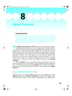
1 BJT Am p l i f i e r s6 CHAPTER OUTLINE6 1 Amplifier Operation6 2 Transistor AC Models6 3 The Common-Emitter Amplifier6 4 The Common-Collector Amplifier6 5 The Common-Base Amplifier6 6 Multistage Amplifiers6 7 The Differential Amplifier6 8 Troubleshooting Device ApplicationCHAPTER OBJECTIVES Describe amplifier operation Discuss transistor models Describe and analyze the operation of common-emitter Amplifiers Describe and analyze the operation of common-collector Amplifiers Describe and analyze the operation of common-base Amplifiers Describe and analyze the operation of multistage Amplifiers Discuss the differential amplifier and its operation Troubleshoot amplifier circuitsKEY TERMSVISIT THE WEBSITES tudy aids, Multisim, and LT Spice files for this chapter are available at /careersresources/INTROdUCTIONThe things you learned about biasing a transistor in Chapter 5 are now applied in this chapter where bipolar junction tran-sistor (BJT) circuits are used as small-signal Amplifiers .
2 The term small-signal refers to the use of signals that take up a relatively small percentage of an amplifier s operational range. Additionally, you will learn how to reduce an ampli-fier to an equivalent dc and ac circuit for easier analysis, and you will learn about multistage Amplifiers . The differential amplifier is also APPLICATION PREVIEWThe Device Application in this chapter involves a preampli-fier circuit for a public address system. The complete system includes the preamplifier, a power amplifier, and a dc power supply.
3 You will focus on the preamplifier in this chapter and then on the power amplifier in Chapter 7. r parameter Common-emitter ac ground Input resistance Output resistance Attenuation Bypass capacitor Common-collector Emitter-follower Common-base Decibel Differential amplifier Common mode CMRR (Common-mode rejection ratio) 25523/11/16 6:06 PM256 BJT Amplifiers6 1 Am p l i f i e r Op e rATi O nThe biasing of a transistor is purely a dc operation. The purpose of biasing is to es-tablish a Q-point about which variations in current and voltage can occur in response to an ac input signal.
4 In applications where small signal voltages must be amplified such as from an antenna or a microphone variations about the Q-point are relatively small. Amplifiers designed to handle these small ac signals are often referred to as small-signal completing this section, you should be able to Describe amplifier operation Identify ac quantities Distinguish ac quantities from dc quantities Discuss the operation of a linear amplifier Define phase inversion Graphically illustrate amplifier operation Analyze ac load line operationAC QuantitiesIn the previous chapters, dc quantities were identified by nonitalic uppercase (capital)
5 Subscripts such as IC, IE, VC, and VCE. Lowercase italic subscripts are used to indicate ac quantities of rms, peak, and peak-to-peak currents and voltages: for example, Ic, Ie, Ib, Vc, and Vce (rms values are assumed unless otherwise stated). Instantaneous quantities are represented by both lowercase letters and subscripts such as ic, ie, ib, and vce. Figure 6 1 illustrates these quantities for a specific voltage FIGURE 6 1 Vce can represent rms, average, peak, or peak-to-peak, but rms will be assumed unless stated otherwise.
6 Vce can be any instantaneous value on the addition to currents and voltages, resistances often have different values when a cir-cuit is analyzed from an ac viewpoint as opposed to a dc viewpoint. Lowercase subscripts are used to identify ac resistance values. For example, Rc is the ac collector resistance, and RC is the dc collector resistance. You will see the need for this distinction later. Resistance values internal to the transistor use a lowercase r9 to show it is an ac resistance. An exam-ple is the internal ac emitter resistance, 25623/11/16 6:06 PMAmplifier Operation 257 The Linear AmplifierA linear amplifier provides amplification of a signal without any distortion so that the output signal is an exact amplified replica of the input signal.
7 A voltage-divider biased transistor with a sinusoidal ac source capacitively coupled to the base through C1 and a load capaci-tively coupled to the collector through C2 is shown in Figure 6 2. The coupling capacitors block dc and thus prevent the internal source resistance, Rs, and the load resistance, RL, from changing the dc bias voltages at the base and collector. The capacitors ideally appear as shorts to the signal voltage. The sinusoidal source voltage causes the base voltage to vary sinusoidally above and below its dc bias level, VBQ.
8 The resulting variation in base current produces a larger variation in collector current because of the current gain of the +VCCR1 RER2 RLC2 VbIbRsIcICQVceVCEQVsC1 IBQVBQ FIGURE 6 2An amplifier with voltage-divider bias driven by an ac voltage source with an internal resistance, the sinusoidal collector current increases, the collector voltage decreases. The col-lector current varies above and below its Q-point value, ICQ, in phase with the base current. The sinusoidal collector-to-emitter voltage varies above and below its Q-point value, VCEQ, 1808 out of phase with the base voltage, as illustrated in Figure 6 2.
9 A transistor always produces a phase inversion between the base voltage and the collector Graphical Picture The operation just described can be illustrated graphically on the ac load line, as shown in Figure 6 3. The ac signal varies along the ac load line, which is different from the dc load line because the capacitors are seen ideally as a short to the ac signal but an open to the dc bias. The sinusoidal voltage at the base produces a base current that varies above and below the Q-point on the ac load line, as shown by the of the Q-point was discussed in Chapter 5, Section 5 1.
10 The ac load line intersects the vertical axis (IC) at the ac value of the collector saturation current Ic(sat) and VCEQ0 VCEIbICIcQac load lineVceICQIc(sat)Vce(cuto )IBQ FIGURE 6 3 Graphical ac load line operation of the amplifier showing the variation of the base current, collector cur-rent, and collector-to-emitter voltage about their dc Q-point values. Ib and Ic are on different 25723/11/16 6:06 PM258 BJT Amplifiersintersects the horizontal axis (VCE) at the ac value of the collector-to-emitter cutoff voltage Vce(cutoff).