Transcription of BLACKMER POWER PUMPS INSTRUCTIONS NO. 101-B00
1 BLACKMER POWER PUMPS 961222 INSTRUCTIONS NO. 101-B00 INSTALLATION OPERATION AND MAINTENANCE INSTRUCTIONS Section Effective Replaces 101 Oct 2007 Aug 2007 MODELS: GX2B, , GX3E, GX4B, X2B, , X3E, X4B TABLE OF CONTENTS Page PUMP DATA Technical 2 Initial Pump Start Up 2 INSTALLATION Pre-Installation Cleaning .. 3 Location and 3 Mounting .. 3 Coupling 4 Gear Reducer Alignment GX 4 Pump 4 To Change Pump Rotation .. 4 Check 4 OPERATION Pre-Start Up Check 5 Start Up 5 Running the Pump in Reverse Rotation .. 6 Flushing the 6 Pump Relief 6 Relief Valve Setting and 6 PUMP MAINTENANCE 7 7 Vane 8 Pump 8 Parts 8 Pump 9 GEAR REDUCER MAINTENANCE Gear Reducer Lubrication.
2 11 Oil Seal Replacement ..12 Gear Reducer Disassembly .. 12 Gear Reducer Assembly ..12 PUMP TROUBLE 13 GEAR REDUCER TROUBLE 14 NOTE: Numbers in parentheses following individual parts indicate reference numbers on BLACKMER Parts Lists. BLACKMER pump manuals and parts lists may be obtained from BLACKMER 's website ( ) or by contacting BLACKMER Customer Service. PUMP PUMP PARTS LIST MODEL 2 3 4 GX 101-B01 101-B02 101-B03 101-B04 X 101-B05 101-B06 101-B07 101-B08 SAFETY DATA This is a SAFETY ALERT SYMBOL. When you see this symbol on the product, or in the manual, look for one of the following signal words and be alert to the potential for personal injury, death or major property damage Warns of hazards that WILL cause serious personal injury, death or major property damage.
3 Warns of hazards that CAN cause serious personal injury, death or major property damage. Warns of hazards that CAN cause personal injury or property damage. NOTICE: Indicates special INSTRUCTIONS which are very important and must be followed. NOTICE: BLACKMER PUMPS MUST only be installed in systems, which have been designed by qualified engineering personnel. The system MUST conform to all applicable local and national regulations and safety standards. This manual is intended to assist in the installation and operation of the BLACKMER POWER PUMPS , and MUST be kept with the pump. Pump service shall be performed by qualified technicians ONLY. Service shall conform to all applicable local and national regulations and safety standards.
4 Thoroughly review this manual, all INSTRUCTIONS and hazard warnings, BEFORE performing any work on the pump. Maintain ALL system and pump operation and hazard warning decals. 101-B00 page 2/16 SAFETY DATA Hazardous machinery can cause serious personal injury. Failure to disconnect and lockout electrical POWER or engine drive before attempting maintenance can cause severe personal injury or death Hazardous voltage. Can shock, burn or cause death. Failure to disconnect and lockout electrical POWER before attempting maintenance can cause shock, burns or death Hazardous or toxic fluids can cause serious injury. If pumping hazardous or toxic fluids, system must be flushed and decontaminated, inside and out, prior to performing service or maintenance Hazardous pressure can cause personal injury or property damage Disconnecting fluid or pressure containment components during pump operation can cause serious personal injury, death or major property damage Do not operate without guard in place Operation without guards in place can cause serious personal injury, major property damage, or death.
5 Hazardous pressure can cause personal injury or property damage Failure to relieve system pressure prior to performing pump service or maintenance can cause personal injury or property damage. PUMP DATA PUMP IDENTIFICATION A pump Identification tag, containing the pump serial number, number, and model designation, is attached to each pump. It is recommended that the data from this tag be recorded and filed for future reference. If replacement parts are needed, or if information pertaining to the pump is required, this data must be furnished to a BLACKMER representative. TECHNICAL DATA 2 , 3 , 4" Maximum Pump Speed 780 RPM 640 RPM Maximum Viscosity 20,000 SSU (4,250 cP) Maximum Operating Temperature * 240 300 F (115 149 C) Maximum Differential Pressure 125 psi ( Bar) Maximum Working Pressure 175 psi ( Bar) * Maximum operating limits are dependent on the materials of construction.
6 See BLACKMER Material Specs 101-095. INITIAL PUMP START UP INFORMATION Model No.: _____ Serial No.: _____ ID No.: _____ Date of Installation: _____ Inlet Gauge Reading: _____ Discharge Gauge Reading: _____ Flow Rate: _____ 101-B00 page 3/16 INSTALLATION NOTICE: BLACKMER PUMPS must only be installed in systems designed by qualified engineering personnel. System design must conform with all applicable regulations and codes and provide warning of all system hazards. Hazardous voltage. Can shock, burn or cause death. Install, ground and wire to local and National Electrical Code requirements. Install an all-leg disconnect switch near the unit motor. Disconnect and lockout electrical POWER before installation or service Electrical supply MUST match motor nameplate specifications.
7 Motors equipped with thermal protection automatically disconnect motor electrical circuit when overload exists. Motor can start unexpectedly and without warning. PRE-INSTALLATION CLEANING NOTICE: New PUMPS contain residual test fluid and rust inhibitor. If necessary, flush pump prior to use. Foreign matter entering the pump WILL cause extensive damage. The supply tank and intake piping MUST be cleaned and flushed prior to pump installation and operation. LOCATION AND PIPING Pump life and performance can be significantly reduced when installed in an improperly designed system. Before starting the layout and installation of the piping system, review the following: 1. Locate the pump as near as possible to the source of supply to avoid excessive inlet pipe friction.
8 2. The inlet line MUST be at least as large as the intake port on the pump. The inlet piping should slope downward to the pump without any upward loops. Eliminate restrictions such as sharp bends; globe valves, unnecessary elbows, and undersized strainers. 3. It is recommended a strainer be installed in the inlet line to protect the pump from foreign matter. The strainer should be located at least 24" ( ) from the pump, and have a net open area of at least four times the area of the intake piping. For viscosities greater than 1000 SSU, consult the strainer manufacture INSTRUCTIONS . Strainers must be cleaned regularly to avoid pump starvation. 4. The intake system must be free of air leaks. 5. Expansion joints, placed at least 36" ( ) from the pump, will compensate for expansion and contraction of the pipes.
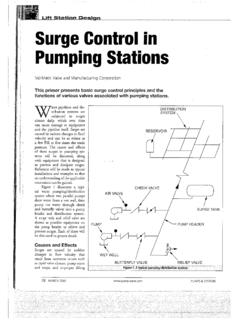
9 Contact the flexible connector/hose manufacturer for required maintenance/care and design assistance in their use. 6. Install pressure gauges in the NPT ports provided in the pump casing to check pump at start up. 7. ALL piping and fittings MUST be properly supported to prevent any piping loads from being placed on the pump. 8. Check alignment of pipes to pump to avoid strains which might later cause misalignment. See Figure 1. Unbolt flanges or break union joints. Pipes should not spring away or drop down. After pump has been in operation for a week or two, completely recheck alignment. Figure 1 9. When pumping liquids at elevated temperature, provisions should be made to compensate for expansion and contraction of the pipes, especially when long pipe lines are necessary.
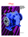
10 Steel pipe expands approximately 3/4 ( cm) per 100 feet ( m) per 100 F ( C) rise in temperature. PUMP MOUNTING A solid foundation reduces noise and vibration, and will improve pump performance. On permanent installations it is recommended the pumping unit be secured by anchor bolts as shown in Figure 2. This arrangement allows for slight shifting of position to accommodate alignment with the mounting holes in the base plate. Figure 2 - Pipe Type Anchor Bolt Box For new foundations, it is suggested that the anchor bolts be set in concrete. When PUMPS are to be located on existing concrete floors, holes should be drilled into the concrete to hold the anchor bolts. When installing units built on channel or structural steel type bases, use care to avoid twisting the base out of shape when anchor bolts are tightened.