Transcription of BODY BUILDER INSTRUCTIONS - Mack Trucks
1 BODY BUILDERINSTRUCTIONSMackTrucksBodybuilder ;Brakesand Air SystemsCHU, CXU, GU, TD, MRU, LRSection5 IntroductionThis informationprovidesdesignand function,specificationand proceduredetailsforBrake and Air Systemsfor :We have attemptedto cover as much informationas , thisinformationdoes not cover all the uniquevariationsthat a vehiclechassismay that illustrationsare typicalbut may not reflectall the variationsof data providedis basedon informationthat was currentat time of ,this informationis subjectto that no part of this informationmay be reproduced,stored,or transmittedbyany meanswithoutthe expresswrittenpermissionof MACKT rucks, : Air brake System ,page 2 Air SolenoidValves ,page 4 LiftableAxle Air SystemRequirements ,page 7 Air Lines JoystickControl ,page 15 Air Line Hose Installation ,page 16 Air Lines Routing ,page 23 Air brake RoutingSchematics ,page 34 Air Line Numbersand Description ,page 46 Air Tank Fittings ,page 52 BrakeLiterature ,page 53 MackBodyBuilderInstructionsCHU,CXU,GU, TD, MRU, (54)All RightsReservedAir BrakeSystemAir brake SystemMVSSR equirementsMVSSC omplianceAs manufacturedby MACKT rucks,Inc.
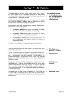
2 , the air brake systemon mack chassis(both incompleteand complete)complywiththe applicablerequirementsof Federaland CanadaMotor Vehicle SafetyStandards(MVSS)106, brake Hoses,and121, Air brake changeor additionto the systemmay causethe vehicleto no longerbe in compliancewiththese requirementscover (but are not limitedto) the following: Air compressorbuild-uptime Air reservoirvolume Servicebrake stoppingdistance brake actuationtime brake releasetime Parkingbrake hold on grades Emergencybrake stoppingdistanceFor a completelist of certificationrequirements,refer to FederalMVSS121 or CanadaMVSS121. Thesemotor vehiclesafetystandardscan be accessedat the followingweb addresses: is the responsibilityof the body/equipmentinstaller/altererto ensurethat the mack vehicleremainsin compliancewith is also the responsibilityof the body/equipmentinstaller/altererto complywith applicablevehiclecertifica-tion brake SystemTruck TractorThere are basic differencesbetweenstraighttruck and truck tractorair a straighttruck, a springbrake controlvalve is addedto the emergencybrake air gives the driver modulatedcontrolof the springbrakesthroughthetreadlevalve in the event of a primarysystemair loss.
3 Additionally, springbrake chambersare installedon both axles of atandemrear axle unit so that if there is a partialair systempressureloss, the emergencybrake systemwill stop the vehiclewithin the requiredstoppingdistance,and also to meet parkingbrake truck air systemis designedto be operatedas that of a truck , and a truck tractorair systemis designedto be operatedasthat of a truck tractor. When convertingchassisfor use other than as originallyintended( , convertinga truck tractorto atruck),the air systemmust also be changedto ensurethat the vehicleremainsin compliancewith ,Inc. ProductSupportfor more ,CXU,GU, TD, MRU, ;Brakesand Air SystemsPage2 (54)All RightsReservedAir-OperatedEquipmentAddit ionalair systemcapacitymay be requiredfor air-poweredaccessoriesto operateproperlywithoutjeopardizingthe in-tegrityof the air brake Vehicle SafetyStandards(MVSS)121 requiresan air capacity12 times the total vol-ume of all air brake chamberson the additionalinformationon calculatingtotal air volumeand brake chamberrated air volumes,refer to LiftableAxle Air SystemRequirementssectionin this additionalair capacityis required,an expansionreservoirshouldbe reservoirand pipingmust.
4 When makingany modificationsto the vehiclethat involvesthe additionof air springs( , liftabletag or pusheraxleshavingair suspensions),the air springsshouldbe suppliedby a pressureprotectedair sourceso that the air brake systemisprotected(to the settingof the pressureprotectionvalve)againstair loss shoulda leak developin the CompressorCapacityIf increasedair systemvolumeis necessary, it is also necessaryto determineif the air compressorhas the capacityto supplythe air systemwithouthavingto run in the loadedmode (compressing)for long periodsof time. Motor Vehicle SafetyStand-ards (MVSS)121 requiresthat the air compressormust be able to increasepressurein the supplyand service(primaryandsecondary)reservoirsfr om 586 690 kPa (85 100 psi), with the enginerunningat maximumgovernedRPM, in a specificamountof time, dependingon requiredand actualreservoircapacity.
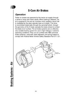
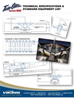
5 If the existingcompressorcannotaccomplishthis, alarger compressormust be used. First, however, make sure that an air compressormalfunctionor other type of problemwiththe air systemis not causingthe slow may be calculatedas SystemBuild-upTimeMackBodyBuilderInstruc tionsCHU,CXU,GU, TD, MRU, ;Brakesand Air SystemsPage3 (54)All RightsReservedAir SolenoidValvesMACK chassisnow incorporateelectricallyoperatedair solenoidvalvesto direct air pressureto the variousaccessoryair cir-cuits such as air suspensioncontrol,fifth wheel slide, inter-axlelockout,powertakeoff(PTO),etc. Additionalair solenoidvalvescan be addedto the air solenoidvalve pack which is locatedon the right-handframe rail, mountedbehindthe 1 Air SolenoidValve Pack LocationTo add an air solenoidto the solenoidvalve pack, disconnectthe valve pack connectorfrom the chassisharness,and thenremovethe valve pack from the end cap from the valve back by twistingthe cap counterclock-wise.
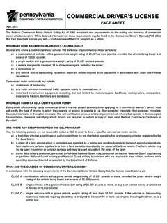
6 Engagethe new solenoidinto the lockingring of the last solenoidin the pack, and then twist the solenoidclockwisetolock the solenoidstogether. Reinstallthe end cap in the same 2 AssemblingSolenoidValveMackBodyBuilderIn structionsCHU,CXU,GU, TD, MRU, ;Brakesand Air SystemsPage4 (54)All RightsReservedRun the wires for the new solenoid(s)along the existingvalve pack harness,and then connectthe terminalends for the sole-noid(s)into the appropriatecavities(pins D and S for the PTO controlsolenoidand pins K and N for neutralcontrol)of thevalve pack connectorbody. The followingtable lists the solenoidvalve pack pin assignments:W5032565 Fig. 3 Air SolenoidValve Pack ConnectorPin AssignmentsPin + PinDescriptionBLInter-WheelLockCRAir SuspensionControl(dumpvalve)DRPTO ControlESInter-AxleLockFRInside/OutsideA irGMFifth WheelReleaseHAFifth WheelSlideKNAir Horn or NeutralControlJRAuxiliaryAxle 1 JRFirst Lift AxleGMSecondLift AxleJRFirst Lift AxleGMSecondLift AxlePMThird Lift AxleMackBodyBuilderInstructionsCHU,CXU,G U, TD, MRU.
7 Brakesand Air SystemsPage5 (54)All RightsReservedAir SolenoidValve Pack Connectorand Pin Part NumbersShouldreplacementof the valve pack connectorbody, pins, seals and plugs be necessary, refer to the followingillustrationfor the applicablepart 4 ConnectorComponentPart NumbersKeyPart (for unusedconnectorcavities)420387692 ConnectorbodyMackBodyBuilderInstructions CHU,CXU,GU, TD, MRU, ;Brakesand Air SystemsPage6 (54)All RightsReservedLiftableAxle Air SystemRequirementsInstallationof a liftableaxle(s)may requireadditionalair capacityfor operationof the servicebrakes,up/downair bags andsuspensionair :The additionof a liftableaxle increasesthe load carryingcapacityof the vehicle,which may affect the ability of theparkingbrake systemto hold the vehicleon a hill.
8 Motor Vehicle SafetyStandard(MVSS)121 requiresthat the parkingbrakesystembe capableof holdingthe vehicleunder ensurecontinuedcompliancewith MVSS121 whena liftableaxle is added,it may be necessaryfor the installerto increasethe capacityof the parkingbrake systemto accountfor the increasein the gross vehicleweightrating (GVWR).LiftableAxle Air Federaland CanadaMotor Vehicle SafetyStandard(MVSS)121 requiresthat total air capacityfor the vehiclemust be12 times the total volumeof all air chambers(front and rear chambersand liftableaxle air brake chambers).As an example,a standardchassishavingfour type-30servicebrake chamberson the rear axles and two type-24servicebrake chamberson the front axle would requirea total air systemcapacityof 5,880 cubic inches,excludingair requirementsfor the liftableaxle brake 5 CalculatingAir SystemCapacityMackBodyBuilderInstruction sCHU,CXU,GU, TD, MRU.
9 Brakesand Air SystemsPage7 (54)All RightsReservedThe additionof two type-24brake chambersfor the liftableaxle installationwould requirean additional1,608 cubic inchesofair 6 CalculatingAir SystemCapacitywith AdditionalChambersfor LiftableAxleTotal air systemcapacityfor the chassis,includingthe additionalcapacitiesfor the two type-24brake chambers,would be7,488 cubic followingtable from MVSS121 lists the brake chamberrated volumesat kPa (100 psi) for the lengthof strokeforeach (NominalArea of Pistonor DiaphragmSquarein)Full Stroke(in)RatedVolume(Cubicin)Type ,CXU,GU, TD, MRU, ;Brakesand Air SystemsPage8 (54)All RightsReservedMVSS121 requiresthat the combinedvolumeof all servicereservoirsand supplyreservoirsbe at least 12 times the com-bined volumeof all servicebrake each brake chambertype havinga full strokeat least as great as the firstnumberin Column1 of the table above,but no more than the secondnumberin Column1 of the table above,the volumeofeach brake chamberfor purposesof calculatingthe requiredcombinedserviceand supplyreservoirvolumeshall be eitherthat specifiedin Column2 of the table aboveor the actualvolumeof the brake chamberat maximumtravel of the brake pis-ton or push rod, whicheveris lower.
10 The volumeof a brake chambernot listed in the table above,is the volumeof the brakechamberat maximumtravel of the brake pistonor push rod. The reservoirsof the truck portionof an auto transporterneednot meet this requirementfor expansionreservoirmust be addedto the air systemto supplyair pressurefor the brakingand up/downfunctionsof a lift-able axle(s).The expansionreservoirfor the liftableaxle brake functionmust be suppliedby the primaryair system,and sup-ply to the expansionreservoirshouldincludea one-waycheck valve to protectthe liftableaxle air systemshoulda leakdevelopin the primaryair , supplyto the liftableaxle(s)controlvalvesfor suspensionfunctionshouldbesuppliedby the secondaryair systemand shouldalso includea pressureprotectionvalve.