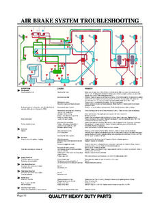
Transcription of S-Cam Air Brakes - Trailer Parts 4U
1 -42- S-Cam Air BrakesOperationTrailer air Brakes are operated by the tractor air supply through a series of relay and check valves. When braking is desired, the air is supplied to the axle air chamber which applies a force that is multiplied by the slack adjuster lever arm length. This force is transmitted rotationally through the camshaft which, through the geometry of the S-head, spreads the brake shoes to contact the brake drum surface. The air brake systems are an effective, very durable braking system for use in high mileage or extreme operating conditions. They can be outfitted with ABS (anti-lock brake systems), automatic slack adjusters and spring Brakes to comply with Federal Motor Vehicle Safety Standard Part RodLength@ RestBraking Systems - Air-43-Braking Systems - AirAir brake ComponentsAir ChambersThe air chambers convert the compressed air into a mechanical force on the slack adjuster.
2 The force on the slack adjuster operates on the end of the lever and converts the chamber output force to a torque on the S-Cam . Federal and state regulations state the maximum pushrod stroke length as an indication of brake adjustment. This stroke is shown by the maximum stroke indicator located on the air chamber pushrod. Maximum allowable stroke is achieved when the indicator is fully extended from the air chamber : Due to manufacturing tolerances, some Brakes may not meet the maximum stroke length in the green state and may require several burnish stops to allow the brake shoes to conform to the drum BrakeFor parking and emergency braking purposes, a spring brake chamber can be used in conjunction with the standard air chamber.
3 The spring brake contains an additional air diaphragm and a very strong spring. When air is applied to the spring brake , the spring is held in the off position by the air diaphragm. When the air is exhausted, the spring provides the braking force to the air chamber pushrod, thus actuating the Brakes .!CAUTIONDo not disassemble the spring brake ! It contains a compressed spring that may cause injury if removed. The spring brake must be caged before servicing and should only be performed by qualified personnel. -44-Slack AdjustersThe air brake slack adjusters perform two functions: (1) The slack adjuster acts as a lever arm to convert the linear pushrod force to rotational camshaft torque.
4 The length of the slack adjuster determines the amount of torque multiplication provided from the pushrod. (2) Allows a simple external adjustment of the lining to drum clearance to compensate for shoe lining wear. There are two types of slack adjusters, manual and automatic:Manual slack adjustersThe manual slack adjusters require manual adjustment to compensate for the brake lining wear and the associated drum to lining gap that results. Adjustment is usually performed by rotating the hex adjusting nut on the slack adjuster body to set a lining to drum clearance of about . ". See instructions for manual slack adjustment slack adjusterThe automatic slack adjuster (ASA) maintains an optimum clearance between the brake lining and the drum by automatically adjusting on the return stroke during brake application.
5 Various brands of ASA s may work differently. The initial adjustment and set-up of the ASA s is critical to proper function of the air brake . See instructions for slack adjuster procedure. Note: Automatic slack adjusters are required on some commercial trailers over 26,000 lbs., manufactured after 10/20/94 per FMVSS Part DO NOT REPLACE AUTOSLACKS WITH MANUAL SLACK ADJUSTERS ON THESE S-cams rotate from the torque applied by the slack adjusters, resulting in spreading the brake shoes which applies the braking force to the drum. The S-cams are supported by two nylon, grease lubricated bushings. Due to the high forces exerted on the cam bushings, periodic inspection, lubrication and maintenance is required to achieve proper braking Systems - Air-45-Braking Systems - AirBrake ShoesThe air brake shoes are the final link in the braking system.
6 The brake shoes are supported by pins inserted into the brake spider, and rollers that contact the S-Cam surface. The shoes have a replaceable lining riveted to them. The linings have two different blocks, designated Cam and Anchor side. The brake shoes on your Dexter axle are specifically designed for that axle. Only Dexter authorized Parts should be used for replacement since there are small dimensional differences between air brake Parts suppliers that can significantly affect the function of the brake .!CAUTIONI mproperly fitted brake Parts can cause Brakes to malfunction and cause loss of braking and/or wheel lockup.
7 Loss of braking can cause an accident resulting in injuries or x 7" Q Style brake Shoefor 9-15K Service Manual (air brake section)-46-General Maintenance/AdjustmentBrake Component LubricationCamshaft bushingsLubricate with approved grease through the grease fittings at the spider and camshaft support bracket locations. Apply just enough grease so grease is visible flowing past camshaft bushing seals. During this process it is advisable to grab the camshaft and shake the camshaft to see if there is excessive clearance in the camshaft bushings due to roller journals and brake anchor pinsThese components are to be lubricated with a high temperature anti-seize grease upon disassembly, maintenance and reassembly.
8 Manual and automatic slack adjustersLubricate with Lithium base NLGI Grade 1 anti-wear grease with rust and oxidizer additives applied at intervals of 3 to 6 months or 50,000 miles or per slack adjuster manufacturer s Pins and Roller Journals Lubricate with high temperature anti-seize grease Spider andSupport BushingsLubricate with NLGI Grade 2 For Manual Slack AdjustersLubricate with NLGI2 For Automatic Slack AdjustersLubricate with ASA manufacturers recommended lubricantBraking Systems - Air-47-Braking Systems - Air12 " Quick Change Brakes - PQ Recommended Disassembly1.
9 Block and secure Trailer on adequate capacity jack stands. Follow Trailer manufacturers recommendations for lifting and supporting the unit. Check that the wheel and drum rotate Release brake and back off slack Remove wheel Lift top shoe upward to disengage the shoe webs from the anchor pin. Remove anchor Repeat procedure 4 for the bottom Remove brake keeper Unwrap bottom shoe by pivoting the shoe on the camshaft head and twisting the shoe 90 under the spindle. Remove shoe assemblies from Remove slack adjuster lock ring, disconnect slack clevis, and then remove slack Remove camshaft lock ring, spacer washer(s) and Completely inspect all brake components, servicing as Reassembly1.
10 Install new camshaft bushing. Ream bushing to if required. Install camshaft seals into the spider. Note: When installing camshaft seals, the seal on the slack adjuster side is installed with seal facing into spider. This allows grease to purge outside the brake assembly when greasing the camshaft bushing. It also aids to avoid damage of the seal lip when camshaft is Install new cam roller assemblies onto the brake shoes. Note: The head of roller pin should face the camshaft D washer once shoes are installed on Systems - Air3. Install D shaped camshaft washer onto the Install the camshaft into the spider.