Transcription of Bonding to the Chip Face - Engineering Training Courses
1 Bonding to the chip Face Wire Bonding is used throughout the microelectronics industry for interconnecting dice, substrates and output pins. Fine wires, generally of aluminium or gold 18 50 m in diameter, are attached using pressure and ultrasonic energy to form metallurgical bonds. Devices bonded with gold wire generally need additional thermal energy, and the Bonding process is referred to as thermosonic rather than ultrasonic . Although many alternative joining methods have been devised, the development of automated, high speed, high throughput equipment has maintained the position of wire Bonding as the principal interconnect process. There are two main bond geometries: Wedge Bonding , most commonly used with aluminium wire, which has a stitch bond at both ends Ball Bonding , generally used with gold wire, where a ball bond is formed at one end and a fish tail bond at the other, the capillary cutting through the wire to produce a single tail-less bond.
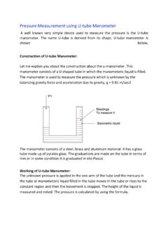
2 Wedge bonds Stitch bonds are formed at both ends of the interconnect by a combination of pressure and vibration. An ultrasonic transducer and horn are designed to translate electrical energy into tool movement along the horn axis. As this energy softens the wire, freshly exposed metal in the wire comes in contact with the freshly exposed metal on the pad and a metallurgical bond is formed. The Bonding dwell time is typically 20ms for an automatic bonder. In Figure 1, which is an SEM photograph of a typical ultrasonic wedge bond, distortion of the wire is visible, but there is no evidence of a weld fillet . This contrasts with soldering operations. Figure 1: SEM photograph of an aluminum ultrasonic wedge bond formed on an IC bond pad Figure 2: The sequence of forming an ultrasonic wedge bond The operation starts by threading the wire through the Bonding tool, known as the wedge , ensuring that the wire is directly underneath the foot of the wedge and projects slightly in front of the toe.
3 The repetitive Bonding cycle (Figure 2) has three parts: First bond . The wedge is moved directly above the target pad, and then lowered. Clamps behind the wedge grip the wire. When the wire is sensed as having touched the bond pad, ultrasonic energy is transmitted to the wedge. The foot of the wedge, which may be grooved, presses the wire and ensures that the energy is dissipated at the wedge-pad interface. The profile and finish of the wedge, and the energy and pressure applied, control the deformation of the wire. Looping . The wire clamps are released, and the wedge is raised and simultaneously moved backwards towards the second bond target pad, creating a wire loop without stressing the first bond.
4 Second bond . The wedge is lowered, using ultrasonic energy and pressure to deform the wire and form the second bond. The wire clamps then grip the wire and are moved backwards so that the wire breaks at the heel of the wedge. The tool is then raised and the wire clamps moved forward so that a short length of wire again projects in front of the tool. The wedge must be moved directly backwards, and not at an angle to the wire, to avoid applying a detrimental torsional shear force to the first bond and to ensure that the wire remains under the tool so that a second bond can be made,. It is necessary therefore, before making the first bond, to bring the points to be joined in line with the tool movement.
5 This can be accomplished by moving either the work or the Bonding head. Ball Bonding Ball Bonding uses the same friction welding principle as wedge Bonding , with an ultrasonic horn which produces a rapid translational movement of the tool. The differences are that: The wire is located centrally in a tubular tool known as a capillary : Figure 3 shows the tip of a capillary viewed from underneath. Because the tool has a circular cross-section, a fish tail (Figure 4) rather than a wedge bond is produced at the other end of the wire. Additional thermal energy is needed, and ball bonders normally heat both die and lead-frame. Figure 3 (left): View of a capillary from the underside Figure 4 (right): A fishtail bond The operation starts by threading the wire through the Bonding tool and forming a ball by melting the protruding wire end (Figure 5).
6 The diameter of the ball is usually just over twice that of the wire from which it was made. This process is known as flame-off because early machines used a small hydrogen flame for this function: the task is now carried out by capacitance discharge, referred to as Electronic Flame-Off (EFO). Figure 5: The ball Bonding sequence Inset shows the function of the capillary F The repetitive Bonding cycle has four parts: First bond . The capillary is moved directly above the target pad, and then lowered. This pulls the ball into the chamfer at the end of the capillary, centring it and tensioning the wire.
7 When the ball is sensed as having touched the bond pad, ultrasonic energy is transmitted to the capillary. The inside surface of the capillary grips the ball and ensures that the energy is dissipated at the ball-pad interface. The inner profile and finish of the capillary, and the energy and pressure applied, control the shape of the ball after Bonding . A typical Bonding time is 20ms with 80gm-force applied. Looping . The capillary is raised and then moved towards the second bond target pad, leaving wire in a loop. In order to control the shape of this loop and optimise the strength of the bond without stressing the wire, automatic machines employ complex tool trajectories. For this reason, a Bonding sequence with loop control may take a total of 200ms.
8 In a typical machine, the capillary is raised to the kink height and then moved in the opposite direction to the target pad, bending the short length of wire immediately above the ball slightly away from the target. Then the capillary rises to loop height , and moves towards the target bond pad. This action straightens the portion of the wire above the neck , without breaking it. Second bond . The capillary is lowered, using ultrasonic energy and pressure to deform the wire and form the second bond. The capillary rises to leave a tail of wire exposed beneath the capillary. Clamps close and hold the wire and the clamps and capillary are moved upwards together so that the wire breaks at its thinnest and weakest point, where the sharp edge of the capillary has cut into the wire.
9 A key factor in controlling the shape and quality of the second bond is the outside profile of the tip. Bonding time is as for the first bond, but at higher pressure (around twice the force applied). Forming a new ball . The capillary rises to re-set height , when an electronic flame-off moves close to the tail and an electrical discharge melts the protruding end of the wire. The EFO retracts, and the melted section of wire solidifies to form a new ball. The diameter of the ball is a function of the tail length and the EFO energy, and this requires tight control of the critical parameters of voltage, current and time. During ball formation, the wire is melted and then rapidly solidified.
10 As a result of this annealing process, the structure and hence the properties of the balled wire are different from the original wire, and the weakest part of the bond is the section just above the ball. Ball Bonding experiments have been carried with both copper and aluminium, but their use has been limited by the properties of the oxide coating on these materials. Compared with gold, a higher level of energy is required to produce a ball, and an inert atmosphere has to be used to reduce oxidation during ball formation. Bond assessment Visual inspection is an effective way of assessing the quality of the wire Bonding process. Cracked heels, tearing at the wedge, misplaced wires, inconsistent wire placement, balls not centred on the wire ( golf-clubbing ), or excessive necking above the ball are indicators of a process which is not in control.