Transcription of Brueninghaus Hydromatik Rexroth A4VSG Pump - Victory
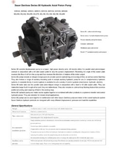
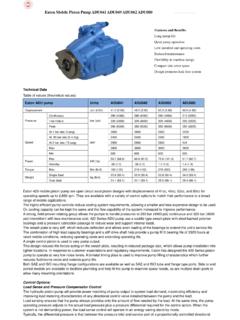
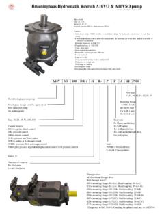
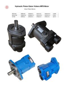
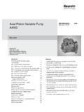
1 Brueninghaus Hydromatik Rexroth A4 VSG Pump Pump model A4 VSG71 A4 VSG125 A4 VSG180 A4 VSG250 A4 VSG355 A4 VSG500 A4 VSG750 A4 VSG1000 Closed circuit variable hydraulic piston A4VG pump Axial piston, swash plate design, variable displacement pump model A4 VSG is designed for hydrostatic transmissions in closed circuit. Flow is proportional to input speed and displacement, and is infinitely variable by adjustment of the swash plate. Nominal pressure 5100 psi (350 bar). Peak pressure 5800 psi (400 bar) Ordering code.
2 A A4VS G 250 DR / 30 -- R P P B 10 N00 1 2 3 4 5 6 7 8 9 1011 12 13 1415 1 Fluid 2 Version 3 Axial piston unit 4 Operation model 5 Size 6 Control device 7 Series 8 Direction of rotation 9 Seals 10 Shaft end 11 Mounting flange 12 Port connections 13 Through drive 14 Valves 15 Filtration More explanation: 1 Fluid: Blank= Petroleum oils E= HF-Fluids (except Skydrol) 2 Version: A = SAE version Blank= Metric version 3 Axial piston unit: Variable pump, swashplate design, industrial applications.
3 4 Operation model: Pump, closed circuit 5 Size: displacement 40, 71, 125, 180, 250, 355, 500, 750, 1000 (cc/rev.) 6 Control device: DR=Constant pressure control LR=Const. Power control with hyperbolic curve MA=Manual control EO=Hydraulic control, with proportional valve HD=Hydraulic control, pilot pressure dependent 7 Series: 10, 22, 30 8 Direction of rotation: R= right. L= left (Viewed on shaft end) 9 Seals: P= NBR (Nitrile rubber to DIN ISO 1629) with shaft seal FPM V= FPM (Fluoride rubber to DIN ISO 1629) 10 Shaft end: P= Metric Parallel with key to DIN 6885 Z= Metric splined shaft per DIN 5480 11 Mounting flange: B= ISO 4-bolt 12 Port connections: 10=Port A,B: SAE on the side (same side), metric mounting threads 13 Through drive.
4 N00= Without auxiliary pump, without through drive K31= ISO 125, 4-hole, Splined shaft 32x2x30x14x9g, A4 VSO/H/G 40 K33= ISO 140, 4-hole, Splined shaft 40x2x30x18x9g, A4 VSO/H/G 71 K34= ISO 160, 4-hole, Splined shaft 50x2x30x24x9g, A4 VSO/H/G 125 K34= ISO 160, 4-hole, Splined shaft 50x2x30x24x9g, A4 VSO/G 180 K35= ISO 224, 4-hole Splined shaft 60x2x30x28x9g, A4 VSO/H/G 250 K99= With through drive, without hub or intermediate flange, with cover closed 14 Valves: 0= Without valve block 9= Valve block SDVB mounted 15 Filtration.
5 N= Without filter F= Filter in boost circuit, mounted Features slot-controlled swashplate design infinitely variable adjustment of displacement reversible flow permissible nominal pressure 350 bar low noise level long service life drive shaft capable of absorbing axial and radial loads operation on HF fluids possible with reduced operating parameters high power/weight ratio modular design short control times through drive and tandem pumps possible pump swivel angle indicator installation position
6 Optional Interchangeable with original Rexroth pump of same model Variable displacement pump A4 VSG, series 1 and 2 Hydraulic Fluid The A4 VSG pumps in the standard design, should be used with good quality, petroleum oil based, anti-wear hydraulic fluids. More detailed information regarding the selection of hydraulic fluids and their application limits can be found in our Data Sheets RA 90 220 (Petroleum Oil), RA 90 221 (Biodegradable Fluids) and RA 90 223 (Type HF Fire Resistant/Synthetic Fluids).
7 When operating with environmentally compatible fluids (Bio- degradable) or Fire Resistant (Type HF synthetic fluids) possible reduction of the operating specifications may be required. Please consult with us and your fluid supplier. Operating Viscosity Range In order to obtain optimum efficiency and service life, we recommend that the operating viscosity (at normal operating temperature) be selected from within the range. Optimum Viscosity ( opt) SUS ( mm2/s) Limits of Viscosity Range The limiting values for viscosity are as follows: Absolute Minimum Viscosity ( min) 60 SUS (10 mm2/s) Only for short periods at max.
8 Permissible leakage oil temperature tmax = 195 F (90 C) Maximum Viscosity ( max) 4600 SUS (1000 mm2/s) Only for short periods during cold start-up Selection Diagram Notes on Hydraulic Fluid Selection In order to select the correct fluid, it is necessary to know the operating temperature in the tank (open circuits) in relation to the ambient temperature. The hydraulic fluid should be selected so that, within the operating temperature range, the fluid viscosity is within the optimum range opt (see shaded area of the selection diagram).
9 We recommend that the higher viscosity grade is selected in each case. Example: At an ambient temperature of X , the operating tempe- rature in the reservoir is 140 F (60 C). In the optimum operating viscosity range opt, (shaded area), this corresponds to viscosity grades VG 46 or VG 68, VG 68 should be selected. Important: The leakage fluid (case drain fluid) temperature is influenced by pressure and speed and is typically higher than the tank temperature. However, maximum temperature at any point in the system must be less than 195 F (90 C).
10 Temperature range (See Selection Diagram) tmin = 13 F ( 25 C) tmax = +195 F (+90 C) Victory Pump Manufacturing pVariable displacement pump A4 VSG, series 1 and 2 Hydraulic Fluid (continued) Bearing flushing For a reliable continuous operation bearing flushing is required with the following operating conditions: Applications with special fluids (non mineral) due to limited lubricity and narrow temperature range operation with mineral oils, however with marginal conditions for temperature and viscosity with vertical mounting (shaft up).