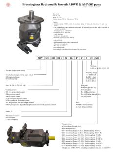
Transcription of Brueninghaus Hydromatik Rexroth A6VM Motor
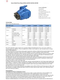
1 Brueninghaus Hydromatik Rexroth a6vm Motor Hydraulic Variable Motor A6VM55, A6VM80, A6VM107, A6VM140, A6VM160, A6VM200, A6VM250. Features Variable Motor with an axial tapered piston rotary group of bent-axis design for hydrostatic drives in open and closed circuits For use in mobile and stationary application areas Series 6 The wide control range enables the variable Motor to satisfy the requirement for high speed Size Nominal pressure : 350 bar and high torque. Peak pressure : 400 bar The displacement is infinitely variable from Vg max to Vg min = 0. Open and closed circuits The output speed depends on the flow of the pump and the displacement of the Motor . The output torque increases with the pressure differential between the high and low pressure side and with increasing displacement.
2 Wide control range with hydrostatic transmission Wide selection of control devices Cost savings through elimination of gear shifts and possibility of using smaller pumps Compact, robust bearing system with long service life High power density Good starting characteristics Low moment of inertia Victory Hydraulic Pump Manufacturing Ordering Code / Standard Program A6V M / 63 W V . 01 02 03 04 05 06 07 08 09 10 11 12 13 14 15 16 17 18 19 20. Hydraulic fluid Mineral oil and HFD. HFD for sizes 250 to 1000 only in combination with long-life bearing "L" (without code). 01 HFB, HFC hydraulic fluid Sizes 28 to 200 (without code). Sizes 250 to 1000 (only in combination with long-life bearing "L") E. Axial piston unit 02 Bent-axis design, variable A6V. Drive shaft bearing 80 107 160 200.
3 Standard bearing (without code) . 03. Long-life bearing L. Operation mode 04 Motor (plug-in- Motor A6VE see RE 91606) M. Size 05 Displacement Vg max in cm3 28 55 80 107 140 160 200 250 355 500 1000. Control device 28 55 80 107 140 160 200 250 355 500 1000. Hydraulic control, p = 10 bar HD1. pilot- pressure related p = 25 bar HD2. p = 35 bar HD3. Hydraulic two-point control HZ. HZ1. HZ3. Electric control, proportional 12V EP1. 24V EP2. Electric two-point control 12V EZ1. 24V EZ2. 12V EZ3.. 06. 24V EZ4. Automatic control, Without pressure increase HA1. high- pressure related With pressure increase p = 100 bar HA2. Hydraulic control, speed related pSt/pHD = 3/100, Hydraulic travel direction valve DA. pSt/pHD = 5/100, Hydraulic travel direction valve DA1. Electric travel direction valve 12V DA2.
4 + electric Vg max control 24V DA3. pSt/pHD = 8/100, Hydraulic travel direction valve DA4. Electric travel direction valve 12V DA5. + electric Vg max control 24V DA6. pressure control (only for HD, EP) 28 55 80 107 140 160 200 250 355 500 1000. Without pressure control (without code) . pressure control, Direct D. 07. Direct, with 2nd pressure setting 1) 1) 1) 1) E. Remote G. Victory Hydraulic Pump Manufacturing Ordering Code / Standard Program A6V M / 63 W V . 01 02 03 04 05 06 07 08 09 10 11 12 13 14 15 16 17 18 19 20. Overriding HA control (for HA1, HA2 only) 28 55 80 107 140 160 200 250 355 500 1000. Without override (without code) . Hydraulic override T. Electric override 12V U1. 08. 24V U2. Electric override 12V R1. + electric travel direction valve 24V R2.
5 Series 09 Series 6, index 3 63. Direction of rotation 10 Viewed from shaft end, alternating W. Setting range for displacement 2) 28 55 80 107 140 160 200 250 355 500 1000. Vg min = 0 to Vg max (without code) . 11 Vg min = 0 to Vg max Vg max = Vg max to Vg max 1. Vg min > Vg max to Vg max Vg max = Vg max to Vg max 2. Seals 12 FKM (fluor-caoutchouc) V. Shaft end 28 55 80 107 140 160 200 250 355 500 1000. Splined shaft DIN 5480 A. 13 Z. Parallel keyed shaft DIN 6885 P. Mounting flange 28 55 80 107 140 160 200 250 355 500 1000. 4-hole ISO 3019-2 B. 14. 8-hole ISO 3019-2 H. Service line ports 3) 28 55 80 107 140 160 200 250 355 500 1000. SAE flange ports 01 0 010. A/B, rear 7 017. SAE flange ports 02 0 020. A/B side, opposite 7 027. 15 Port plate for mounting a counterbalance valve on request 08 0 080.
6 SAE flange ports A/B side, opposite + rear 15 0 150. Port plate with pressure -relief valves, 37 0 . 370. For mounting a counterbalance valve 4) 5) 38 0 380. Valves Without valve 0. With flush and boost pressure valve 7. Victory Hydraulic Pump Manufacturing Ordering Code / Standard Program A6V M / 63 W V . 01 02 03 04 05 06 07 08 09 10 11 12 13 14 15 16 17 18 19 20. Speed measurement 28 55 80 107 140 160 200 250 355 500 1000. Without speed measurement (without code) . 16 Prepared for speed measurement (ID) 6) D. Prepared for speed measurement (HDD) 6) F. Swivel angle indicator 28 55 80 107 140 160 200 250 355 500 1000. Without swivel angle indicator (without code) . 17 With optical swivel angle indicator V. With electric swivel angle indicator E. Connector for solenoids (only sizes 28 to 200) 7) EP1/2 EZ1/2 EZ3/4 ) DA.
7 DEUTSCH - molded connector, 2-pin without suppressor diode P. 18 DEUTSCH - molded connector, 2-pin withsuppressor diode Q. HIRSCHMANN - connector without suppressor diode H. Start of control 28 55 80 107 140 160 200 250 355 500 1000. At Vg min (standard for HA) A. 19. At Vg max (standard for HD, HZ, EP, EZ, DA) B. Standard / special version9). Standard version (without code). With attachment part -K. 20. Special version -S. With attachment part -SK. 1) Supplied as standard with version D. 2) Please specify precise setting for Vg min and Vg max in plain text when ordering: Vg min = .. cm3, Vg max = .. cm3. 3) Metric fixing thread 4) Only possible in combination with HD, EP, HA control 5) With and for the 2nd solenoid ( 45), the version with DEUTSCH molded connector is available on request.
8 6) Adjustment data are included in the material number RE 91604 a6vm Series 63 Bosch Rexroth AG 5/80. Technical data Hydraulic fluid Details regarding the choice of hydraulic fluid Before starting project planning, please refer to our data The correct choice of hydraulic fluid requires knowledge of the sheets RE 90220 (mineral oil), RE 90221 (environmentally operating temperature in relation to the ambient temperature: in acceptable hydraulic fluids), RE 90222 (HFD hydraulic fluids) a closed circuit, the circuit temperature, in an open circuit, the and RE 90223 (HFA, HFB, HFC hydraulic fluids) for detailed reservoir temperature. information regarding the choice of hydraulic fluid and applica- The hydraulic fluid should be chosen so that the operating tion conditions.
9 Viscosity in the operating temperature range is within the The variable Motor a6vm is not suitable for operation with optimum range ( opt see shaded area of the selection diagram). HFA hydraulic fluid. If HFB, HFC, or HFD or environmentally We recommended that the higher viscosity class be selected acceptable hydraulic fluids are used, the limitations regarding in each case. technical data or other seals must be observed. Example: At an ambient temperature of X C, an operating tem- perature of 60 C is set in the circuit. In the optimum viscosity Selection diagram range ( opt., shaded area), this corresponds to the viscosity -40 -20 0 20 40 60 80 100 classes VG 46 or VG 68; to be selected: VG 68. 1600 1600. 1000. 600 Note 400 The case drain temperature, which is affected by pressure and speed, can be higher than the circuit temperature or reservoir VG 68.
10 VG. VG 32. VG 46. VG 2. 200. 10. 2. temperature. At no point of the component may the tempera- 0. 100. ture be higher than 115 C. The temperature difference speci- Viscosity [mm2/s]. 60. fied below is to be taken into account when determining the 40 36 viscosity in the bearing. opt 20 If the above conditions cannot be maintained due to extreme 16 operating parameters, we recommend flushing the case at port 10. U or using a flushing and boost pressure valve (see pages 71. and 72). 5 5. -40 -25 -10 0 10 30 50 70 90 115 . tmin = -40 C Hydraulic fluid temperature range tmax = +115 C. Viscosity and temperature of hydraulic fluid Viscosity [mm2/s] Temperature Comment Transport and storage Tmin -50 C factory preservation: up to 12 months with standard, at ambient temperature Topt = +5 C to +20 C up to 24 months with long-term (Cold) start-up1) max = 1600 TSt -40 C t 3 min, without load (p 50 bar), n 1000 rpm (sizes 28 to 200), n nnom (sizes 250 to 1000).