Transcription of Building Blocks - structuremag.org
1 W Building ith widespread acceptance in the Reduces schedule for installation. market place, many engineers are Reduces the cost of a structure needing a choosing ground improvement traditional deep foundation, and its design, Blocks techniques to provide a suitable by replacing pile caps, grade beams and subgrade for shallow foundations at sites that structural slabs with spread footings and would have traditionally required deep foun- slabs-on-grade. dations. This article discusses the Controlled Improves the performance of a methane Modulus Column (CMC) ground improvement barrier system, when required, by eliminating updates and information technique and some case histories highlighting complex detailing around pile caps. the use of this technique.
2 CMCs are a sustainable Eliminates the need to hang utilities under on structural materials and cost-effective ground improvement technol- a structural slab, as utilities are installed ogy that transmit load from the foundation to a directly within the load transfer layer. lower bearing stratum through a compacted soil With CMCs, the slab-on-grade can be built load transfer layer and the composite CMC/soil after the Building is erected, in a controlled matrix. CMCs are constructed using 2000-3000 environment, resulting in a better quality psi grout and range in diameter from 11 to 18 finish. With traditional pile foundations, . E. inches. CMCs have been installed in a variety of the structural slab is typically built before soils including uncontrolled fill, organics, peat, the Building .
3 R. soft to stiff clay, silt, municipal solid waste, and Reduces the carbon footprint associated loose sands. Typically, the CMCs are installed with foundations. U. through the soft or compressible soils and into While CMCs ht are an attractive financial and yrig T. dense sand, stiff clay, glacial till, or other compe- sustainableCopoption, tent material that serves as the bearing stratum. it has also been C Controlled Modulus Columns The CMC installation is an attractive option from demonstrated that e U. an environmental perspective because it utilizes the performance of reverse flight augers, which displace the soil laterally. the system is com- i n R. This installation technique achieves two goals: it parable to that of az An Attractive Alternative T.
4 Densifies the soil around the CMC, which improves deep pile foundations. Typical CMC designs limit load transfer into the element, and it eliminates total settlement of a structure to 1 inch and differ- ag S. spoils and the associated disposal requirements ential settlement to inch. Foundation subgrade By Michael Walker, , and costs. The use of traditional augers, used to is typically evaluated for both strength (bearing Frederic Masse and install auger-cast piles or drilled caissons, might appear to result in a similar foundation system m capacity) and service (settlement). The traditional approach was to use piles to control settlement at Sonia Swift, but would not include the benefits of the CMC sites with poor quality soils. The piles became the installation technique.
5 In addition, the hole cre- supporting elements for the foundation and were ated by the displacement auger is backfilled with designed to resist lateral and vertical loads applied to pressurized cement grout that further densifies the the foundation. However, the pile capacity required surrounding soils. The result is a CMC element to control settlement may be significantly lower that is significantly stiffer than the soil around it. than that required to support the foundations. Therefore, the CMCs attract load from above, and Therefore, the service goal may require an inef- Michael Walker, is a Vice transmit that load to the more-competent deeper ficient system because the pile system ignores the President of GEI Consultants soils or bearing stratum.
6 In the past, CMCs have strength of the soil surrounding the piles. Ground (Woburn, MA), a multi-disciplined been designed with a central steel reinforcing bar, improvement is typically more efficient because team of engineers and scientists. if additional strength is required. its design utilizes the strength of the surrounding Michael may be reached at When selecting the appropriate ground soil and additional soil-improved strength to meet improvement technology, knowledge of the service load requirements. Frederic Masse is Vice President benefits of each system is key. Because CMCs While the use of CMCs for Building foundations of Engineering for Menard are a relatively new technology many potential are provided in the following case studies, CMCs (Bridgeville, PA), a ground users are not aware of their benefits.
7 Some of also have been used for a variety of other applica- improvement services firm. these benefits include: tions including foundations for tanks, mechanically Frederic may be reached at Promotes development of brownfield sites stabilized earth (MSE) walls, and embankments. underlain by poor quality soils. Avoids excavation and replacement of poor Sonia Swift, is a project quality soils and limits spoil, reducing Philadelphia Produce Market engineer at GEI Consultants. waste generation. Ground improvement using Controlled Modulus Sonia may be reached at Avoids driving long steel piles to bedrock. Columns (CMCs) was used at the site of a 550,000 Provides a cost-effective solution compared square-foot warehouse on the southeast corner of to conventional pile foundation systems.
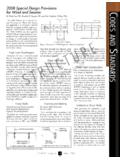
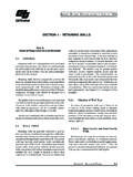
8 Essington Street in Philadelphia, Pennsylvania. Allows for the lengths of CMCs to be The original foundation design proposed the use adjusted in the field without splicing of either 8-inch-diameter timber piles or 12-inch- or cutting. diameter grouted steel pipe piles, both driven to STRUCTURE magazine 13. CMC Installation at the Essington Warehouse Site. Multiple rigs were on site to accelerate the construction schedule. a depth of approximately 50 feet. In addition, thickened reinforced pile caps, internal grade beams, and a 12-inch-thick reinforced, 2-way structural slab would be required to connect the piles to the superstruc- ture. Instead, the warehouse was supported using CMCs drilled to a depth of approximately 35 feet. The CMCs were placed under individual footings and beneath the slab.
9 The CMC . support allowed for the use of spread footings and a 6-inch-thick E. slab-on-grade, and eliminated the need for internal grade beams. R. The main purpose of the CMCs was to minimize the settlement of the warehouse, which could have been significant if some type of U. support was not provided. The Building was constructed over munici- ht pal solid waste and organic soils that were present in the subsurfaceyrig T. Cop profile. CMCs were designed to penetrate the municipal solid waste C. and organic soil and terminate in the dense sand at depth. Because the site was a former landfill, the spoils would likely require e U. special, costly handling for disposal. An obvious advantage to using CMCs, or any displacement installation method, is that no spoils are i n R z generated.
10 In addition, CMCs contain grout only, which is a more T a sustainable material than reinforced concrete or steel. A comparison of g S. the environmental impacts of a pile foundation and the CMC ground improvement showed a 25% reduction in the carbon footprint of the a foundations when using CMCs. m The carbon footprint offset calculation was based on the difference in quantity and carbon footprint values for the concrete, steel, and grout associated with the two different schemes. It does not include any benefits of the accelerated schedule associated with the CMC. design, nor with the additional carbon footprint required to dispose of extra, potentially contaminated, soils associated with the deep foundation scheme. The ground improvement was completed in the summer of 2009, and the structure is in the final phases of construction.