Transcription of Bus Architectures - EOLSS
1 COMPUTER SCIENCE AND ENGINEERING - Bus Architectures - Lizy Kurian John BUS Architectures . Lizy Kurian John Electrical and Computer Engineering Department, The University of Texas as Austin Keywords: Bus standards, PCI bus, ISA bus, Bus protocols, Serial Buses, USB, IEEE. 1394. Contents 1. Introduction 2. Bus Protocols Synchronous and Asynchronous Buses Serial and Parallel Buses S. TE S. Bus Arbitration 3. Bus Standards R. AP LS. Parallel Bus Architectures Serial Buses Bridge Buses C EO. 4. Conclusion Glossary Bibliography E . Summary H. A bus is a common pathway to connect various subsystems in a computer system. A bus PL O. consists of the connection media like wires and connectors, and a bus protocol.
2 Buses can be serial or parallel, synchronous or asynchronous. Depending on these and other M SC. features, several bus Architectures have been devised in the past. The Universal Serial Bus (USB) and IEEE 1394 are examples of serial buses while the ISA and PCI buses are examples of popular parallel buses. This article first describes fundamental SA NE. information on bus Architectures and bus protocols, and then provides specific information on various industry standard bus Architectures from the past and the present, and their advantages and disadvantages. It also describes how different types of bus Architectures are used simultaneously in different parts of a modern personal computer.
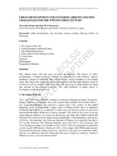
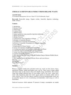
3 U. 1. Introduction A typical computer system is composed of several components such as the Central Processing Unit (CPU), memory chips, and Input/Output (I/O) devices. A bus is a common pathway or a set of wires that interconnect these various subsystems. The bus thus allows the different components to communicate with each other. The concept of a bus is illustrated in Figure 1. A bus, in computer language, is a channel over which information flows between units or devices. It typically has access points, or places into which a device can tap to become part of the channel. Most buses are bidirectional and devices can send or receive information. A bus is a shared communication link between the different Encyclopedia of Life Support Systems ( EOLSS ).
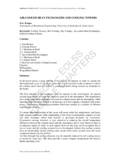
4 COMPUTER SCIENCE AND ENGINEERING - Bus Architectures - Lizy Kurian John devices. It allows to add new devices easily and facilitates portability of peripheral devices between different computer systems. However, if too many devices are connected to the same bus, the bandwidth of the bus can become a bottleneck. Typically more than two devices or subsystems are involved in a bus, and channels connecting only two components are some times referred to as ports instead of buses. S. TE S. Figure 1: The concept of a bus R. AP LS. Buses often include wires to carry signals for addresses, data, control, status, clock, power and ground as illustrated in Figure 2. The address lines indicate the source or destination of the data on the data lines.
5 Control lines are used to implement the bus C EO. protocol. Often there are lines to request bus control, to handle interrupts, etc. Status lines indicate the progress of the current transaction. Clock signals are used in synchronous bus systems to synchronize bus operations. E . H. PL O. M SC. SA NE. U. Figure 2: Different kinds of wires in a bus The communications needs of the different devices in a computer system vary. For instance, fast high bandwidth communication is needed between processors and memory whereas bandwidth requirements are not so high on buses to I/O devices. This has led to the creation of different kinds of buses differing in their width, latency and bandwidth capabilities.
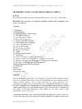
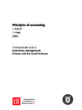
6 Typically there are two kinds of buses, CPU-memory buses and I/O buses. CPU-memory buses are fast and short, and I/O buses are typically long and slow. I/O buses also have many devices connected to them. Some refer to this arrangement as a bus hierarchy with fast buses closer to the processor and slow buses farther away from the processor. Figure 2 illustrates the bus hierarchy in a typical computer that uses the Pentium II processor. Encyclopedia of Life Support Systems ( EOLSS ). COMPUTER SCIENCE AND ENGINEERING - Bus Architectures - Lizy Kurian John S. TE S. R. AP LS. C EO. E . H. PL O. M SC. Figure 3: Buses in a typical personal computer system with Intel Pentium Processor SA NE.
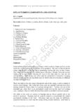
7 U. Figure 4. Simplified sketch of I/O device slots on a motherboard Encyclopedia of Life Support Systems ( EOLSS ). COMPUTER SCIENCE AND ENGINEERING - Bus Architectures - Lizy Kurian John The I/O buses in a personal computer are often etched on to a printed circuit board, which has connector slots to insert the peripheral device card. The I/O device cards have tabs that will fit into the connector, as illustrated in Fig. 4. The tab on the I/O card has metallic strips on each side to make electrical contact with the bus. 2. Bus Protocols A bus is a communication channel shared by many devices and hence rules need to be established in order for the communication to happen correctly.
8 These rules are called bus protocols. Design of a bus architecture involves several tradeoffs related to the width of the data bus, data transfer size, bus protocols, clocking, etc. Depending on whether the bus transactions are controlled by a clock or not, buses are classified into synchronous and asynchronous buses. Depending on whether the data bits are sent on parallel wires or multiplexed onto one single wire, there are parallel and serial buses. S. TE S. Control of the bus communication in the presence of multiple devices necessitates defined procedures called arbitration schemes. In this section, different kinds of buses R. AP LS. and arbitration schemes are described.
9 Synchronous and Asynchronous Buses C EO. In a synchronous bus, bus operations are synchronized with reference to a clock signal. The bus clock is generally derived from the computer system clock, however, often it is slower than the master clock. For instance, 66 MHz buses are used in systems with a processor clock of over 500 MHz. Buses were traditionally slower than processors E . because memory access times are typically longer than processor clock cycles. A bus H. transaction often takes several clock cycles, although the cycles are collectively referred PL O. to by many as a bus cycle. M SC. SA NE. U. Figure 5. Read Operation on a Synchronous Bus Encyclopedia of Life Support Systems ( EOLSS ).
10 COMPUTER SCIENCE AND ENGINEERING - Bus Architectures - Lizy Kurian John A memory read transaction on the synchronous bus typically proceeds as illustrated in Fig. 5. During the first clock cycle the CPU places the address of the location it wants to read, on the address lines of the bus. Later during the same clock cycle, once the address lines have stabilized, the READ request is asserted by the CPU. Many times, some of these control signals are active low and asserting the signal means that they are pulled low. A few clock cycles are needed for the memory to perform accessing of the requested location. In a simple non-pipelined bus, these appear as wait states and the data is placed on the bus by the memory after the tow or three wait cycles.