Transcription of Butternut HF6V - static.dxengineering.com
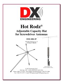
1 Butternut hf6v 80/40/30/20/15 and 10 Meters Six-Band Vertical Antenna BUT- hf6v BUT- hf6v -INS-Revision 1a Butternut 2016 Artists rendition of an installation 1200 Southeast Ave. - Tallmadge, OH 44278 USA Phone: (800) 777-0703 Tech Support and International: (330) 572-3200 Fax: (330) 572-3279 - 1 - Introduction The classic Butternut hf6v 6-band vertical antenna operates on 75/80, 40, 30, 20, 15 and 10 meters.
2 Designed with corrosion-resistant aluminum tubing, this antenna is very durable and attractive. The first L/C circuit generates enough reactance to bring the whole hf6v to resonance on 80 meters allowing it to act as a 1/4-wave radiator. It also generates enough capacitive reactance to produce another discrete resonance at about 11 MHz. The second, 40 meter L/C circuit generates enough reactance to resonate the whole hf6v allowing it to act as a 1/4-wave radiator. In order to minimize conductor and I R losses an 80 and 40 meters where the antenna is physically shorter than a 1/4-wave and thus operates with lower values of radiation resistance, large-diameter Hi-Q self-supporting inductors and low loss ceramic capacitors are employed.
3 Where the height of the hf6v is slightly greater than a 1/4-wave on 30 meters, an L/C series tuned circuit taps onto the 40 meter coil for the extra inductance to pull the earlier 11 MHz secondary resonance down to 10 MHz. At the same time, a portion of the 40 meter coil is shorted out which allows the circuit to resonate on 30 meters The addition of this circuit also produces additional resonances at 14 MHz and 28 MHz. On 20 meters the entire radiator operates as a 3/8-wave vertical with much higher radiation resistance and VSWR bandwidth than conventional or trapped antennas having a physical height of 1/4-wave or less. Because the 20 meter radiation resistance will be several times as greater as that of conventional vertical antennas, an electrical 1/4-wave section of 75 ohm coax is used as a geometric mean transformer to match the approximate 100 ohms of feedpoint impedance on that band to a 50 ohm main transmission line of any convenient length.
4 The hf6v operates as a slightly extended 1/4-wave radiator on 15 meters, a 1/4-wave stub de-coupler providing practically lossless isolation of the upper half of the antenna on that band. On 10 meters the hf6v becomes a 3/4-wave radiator with considerably greater radiation resistance and efficiency than 1/4-wave trapped verticals. Features Full band coverage for 80, 40, 30, 20, 15 and 10 meters Height is 26 feet Weight is only 14 pounds Feedpoint Impedance is a nominal 50 ohms through the included matching line Power handling up to 1,500 W full legal limit on 80/40/20/15/10M, 500 W PEP on 30M Wind load 2 ft2 (80 mph survivability - no ice) VSWR at resonance: or less on all bands Bandwidth for VSWR 2:1 or less: 30/20/15/10M - entire band.
5 Bandwidth for VSWR 2:1 or less: 140-150 kHz on 40M, 25-30 kHz on 75/80M Requires radial system - 2 - WARNING! INSTALLATION OF ANY ANTENNA NEAR POWER LINES IS DANGEROUS Warning: Do not locate the antenna near overhead power lines or other electric light or power circuits, or where it can come into contact with such circuits. When installing the antenna, take extreme care not to come into contact with such circuits, because they may cause serious injury or death. Overhead Power Line Safety Before you begin working, check carefully for overhead power lines in the area you will be working. Don't assume that wires are telephone or cable lines; check with your electric utility for advice.
6 Although overhead power lines may appear to be insulated, often these coverings are intended only to protect metal wires from weather conditions and may not protect you from electric shock. Keep your distance! As a suggestion, remember the 10-foot rule; when carrying and using ladders and other long tools, keep them at least 10 feet away from all overhead lines - including any lines from the power pole to your home. There are parts made from fiberglass in this kit. Take normal precautions when handling any fiberglass material. There may be fiberglass dust, slivers or particles present when the fiberglass parts were manufactured. The use of typical fiberglass handling safety gear (gloves, dust mask, eye shield, clothing, etc.)
7 When handling and working with fiberglass is recommended. Use a damp rag to wipe the parts. Do not use compressed air to clean fiberglass parts. Measures can be taken to reduce exposure after a person has come in contact with fiberglass. Eyes should be flushed with water and any area of exposed skin should be washed with soap and warm water to remove fibers. Clothing worn while working with fiberglass should be removed and washed separately from other clothing. The washing machine should be rinsed thoroughly after the exposed clothing has been washed. Check with your local or state safety and/or environmental agencies for more detailed precautions. Tools Required Straight Slot Screwdriver Phillips Head Screwdriver 1/4 Nut Driver or socket set 11/32 Nut Driver or socket set 3/8 Nut Driver or socket set Tape measure Pencil - 3 - Additional Material Needed But Not Supplied Jet-Lube SS-30 Aniti-Oxidant Corrosion Inhibiting Lubricant Ground Rod installed near base of the antenna Suggested Parts Not Included Radial Wire Kits and Components - There are optional Radial Wire Kits available.
8 Guying Kit for Vertical Antennas - Some vertical antenna manufacturers indicate their antennas do not need guying. During times of high winds or ice loading, some of these vertical antennas may sustain damage or fail altogether. With the small amount of effort needed to install a four point guying system, the risk hardly seems worth taking. A four-point guying scheme provides the best mechanical advantage to reduce wind stress, regardless of direction. Information on guying the Butternut hf6v is included in this manual. Information on guying the Butternut hf6v can be found in the section Guying the hf6v Antenna . BUT-GRK Ground Radial Kit for ground mounting - 160 thru 6 meter operation BUT-RMK-II Roof Mounting Kit for roof mounting - 80 thru 6 meter operation Site Selection Ideally, select a mounting location clear from power lines, structures and other antennas by a minimum of 45 feet.
9 Consider overhead power lines, utility cables and wires. The vertical should be mounted away from local noise sources or other metallic objects which can re-radiate noise and affect the tuning, radiation pattern and SWR. Determine the direction you want the antenna to tilt down and make sure there is adequate clearance (at least 45 feet). There should also be a clear diameter of 70 to 130 feet from the antenna for the guying and radial systems that will extend away from the antenna. As with all Amateur Radio antennas there maybe compromises and the ideal site may not be available. - 4 - Mounting Tube (A) Installation When the bottom tube with insulator (A) is ground mounted, it should be protected against corrosion if placed in concrete, damp acidic or alkaline soil.
10 Asphalt roofing compound, polyurethane varnish or other sealant that protects against moisture may be used. Concrete may be used in areas of high winds for greater strength, in which case the post may be twisted slightly during setting for easy removal later. Ensure it is not mounted at an angle. You want the antenna to be vertical when fully installed. To help maintain the antenna base, place a larger diameter metal tube, such as the BUT-MPS Mounting Post Sleeve in the ground, then you can slip tube w/insulator (A) in and it will be protected from direct contact with the concrete. Tube with insulator (A) must be installed in a hole approximately 21 inches deep so that the upper end of the fiberglass insulator is approximately 7 inches above ground level.