Transcription of Cable plant loss FOA-1a - The Fiber Optic Association
1 2012, The Fiber Optic Association , Inc. Cable plant loss , 11/15/14, 1 FOA Standard FOA-1 Testing loss Of Installed Fiber Optic Cable plant This test will measure the loss of an installed Fiber Optic Cable plant , singlemode or multimode, including the loss of all Fiber , splices and connectors. Equipment Needed To Perform This Test 1. Test source appropriate for the Fiber being tested (Multimode: 850 and/or 1300nm LED, singlemode, 1310 and/or 1550 nm laser) 2. Optical power meter calibrated at the same wavelengths as the source output. 3. Launch and receive reference cables of the same Fiber type and size as the Cable plant and have connectors compatible to those on the Cable plant . They should be tested per FOA-2 to ensure they are in good condition.
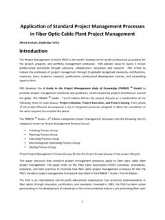
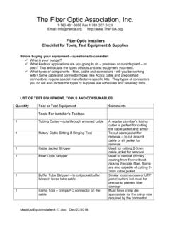
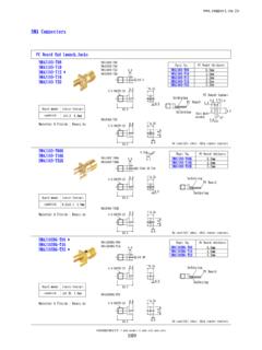
2 4. Mating adapters compatible to connectors 5. Cleaning supplies Test Diagram Test Procedure 1. Turn on equipment and allow time to warm-up 2. Attach launch Cable to source. This should remain connected to source for the duration of the test. 3. Clean all connectors and mating adapters. 4. Set 0 dB reference using method shown to the right. Meter may be set to read 0 dB. 5. Attach source/ref Cable and meter/ref Cable to the Cable plant under test and make loss measurement. Options For 0 dB Reference - Set Before Testing 1. Use the 1 Cable Reference if connectors are the same on the Cable plant as the testers and reference cables or may be adapted using hybrid adapters. 2. Use the 2 Cable Reference if connectors are not the same on the Cable plant as the testers but can be mated to each other with adapters and hybrid reference cables are being used.
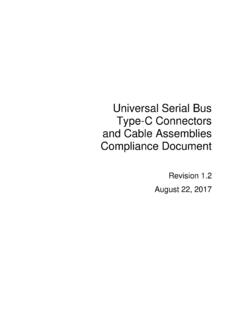
3 3. Use the 3 Cable Reference if connectors are plug/jack styles and reference cables are both ended in either plugs or jacks. Reducing Measurement Uncertainty 1. Clean all connectors regularly before and while testing. 2. Use modal control on launch Cable , small loop on SM Fiber or mandrel wrap on MM Fiber . 3. Check 0 dB Reference periodically during testing. 4. 4. Periodically check reference cables per FOA-2 to verify their condition. Documentation Record the date of the test, operator, test equipment used, reference method, Cable and Fiber identification, test wavelength and measured loss . Setting 0 dB Reference 1 Cable Reference 2 Cable Reference 3 Cable Reference