Transcription of Fiber Optics Lab Manual Instructor’s Manual
1 Fiber Optics Lab Manual instructor s Manual For Classroom and Hands-On Laboratory Sessions Contacts For Assistance You can contact the FOA for questions and advice by phone, fax or email: The Fiber Optic Association, Inc., 1119 S. Mission Ave #355, Fallbrook. CA 92028 Phone: 1-760-451-3655 Fax: 1-760-207-2421 Email: Availability of plastic optical Fiber (POF) The plastic optical Fiber used in some of these experiments is available for science distributors. It is a 1000micron (1mm) POF available from several suppliers. FOA has samples available at no cost for teachers at schools in the US. Contact us at the email above. This information is provided by The Fiber Optic Association, Inc. as a benefit to those interested in teaching, designing, manufacturing, selling, installing or using Fiber optic communications systems or networks.
2 It is intended to be used as a overview and/or basic guidelines and in no way should be considered to be complete or comprehensive. These guidelines are strictly the opinion of the FOA and the reader is expected to use them as a basis for learning, as a reference and for creating their own documentation, project specifications, etc. Those working with Fiber Optics in the classroom, laboratory or field should follow all safety rules carefully. The FOA assumes no liability for the use of any of this material. Fiber Optics Lab Manual PREFACE This series of Fiber Optics laboratory experiments was developed by Professor Elias Awad for the FOA under a NSF grant. It is intended to introduce students in technical high schools and colleges to the technology of Fiber Optics . No previous experience in Fiber Optics is required.
3 Students are expected to read all sections of each laboratory write-up before starting with the procedure section of each experiment. In some cases, the teacher may wish to use this laboratory Manual as a text. We included in each experiment enough theory, tutorial material and examples to fulfill the needs of some programs. Teachers may wish to hold the students responsible to do the exercises provided with the laboratory write-ups. Teachers offering a full semester of Fiber Optics will find it necessary to have a regular textbook for the lecture section of the course. The FOA Textbook, The Fiber Optic Technicians Manual , is one choice, but at a college level, a text with more theory, such as Fiber Optic Communications by Jim Downing or Jeff Hecht s Understanding Fiber Optics Several laboratory write-ups suggested that the students do the experiment with more than one type of Fiber .
4 If this requirement is not fulfilled due to the lack of resources, the educational benefit of the experiment will not be lost. Elias A. Awad email: Lab Exercise 1 1- TITLE: Termination of various lengths plastic optical fibers into a metallic, 1000 m, ST Fiber optic connector for plastic Fiber . 2- OBJECTIVE: This is an exercise. It is intended to develop your Manual dexterity while teaching you the proper installation of an ST connector on the ends of a plastic optical Fiber Students are expected to pay attention to the proper way to install the connector on the Fiber . This must be done in a way that will ensure longevity and prevent premature failure of the Fiber optic link. Students will use room temperature epoxy and mechanical crimping to secure the Fiber firmly into the connector.
5 Oven cured epoxy may not be used with plastic Fiber . Each student (or group of students, depending on the available budget) will prepare 9 optical fibers of various lengths. Later in this Manual , you will use these same fibers to perform other experiments. 3- PURPOSE: We introduced this exercise to teach you the importance of installing connectors on optical fibers. Without connectors, there will be no reliable way to align two fibers. Alignment is important to permit the transmission of an optical signal between two fibers or between a Fiber and a transmit or receive instrument. Connectors are the weakest link for a signal in a Fiber optic line. It is where maximum power losses may be found. You will learn that it is worth your while to understand and practice proper connector installation to avoid unnecessary service calls.
6 Unnecessary service calls may annoy an engineer and will eat away at the profit margin of a contractor who is responsible for the performance of an installation. 4- TUTORIAL: x1 Typically, optical Fiber is made of thin and solid strands of glass. In this case, we are using plastic optical Fiber with 1000 m diameter. The hole in the ST connector is also 1000 m in diameter. Plastic optical Fiber is not popular in long distance nor is it popular in high frequency applications. In long distance applications, it exhibits unacceptable losses, this is called attenuation. In high frequency applications, it exhibits greater pulse distortion, this is called modal distortion. At this writing, a type of plastic optical Fiber called graded index plastic optical Fiber is underdevelopment.
7 It promises to perform satisfactorily at substantially higher frequencies but over a distance of only 100 meters or less. So as you can see, while it may be useable at higher frequencies, its application will continue to be limited to a short distance. : from the street to the home. Not only its higher losses, but also its large core diameter contribute to the poor performance of plastic optical Fiber . In a large core fibers, a large number of modes is transmitted inside the core. Each of these modes will travel a different optical path. These optical paths are unequal. This is what gives rise to modal distortion. Again, none of these optical paths is equal in length. This causes different segments of a single optical signal (one flash of light, one bit) to exit from the output end of the Fiber at different times, thus distorting the optical pulse.
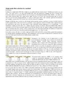
8 This will also cause an overlapping of adjacent optical pulses. one bit input; one flash of light output with a modal distortion two or more bits input output with a modal distortion and pulse overlap The number of modes for each data bit in a multimode Fiber is given by the M number of the Fiber . The M number is given by the V number of the Fiber : x1 M = V2 / 2 True only for values of V 10 V = [(2 a)/ ] n12 - n22 n1 and n2 are the indices of refraction of the core and cladding, respectively. a is the core radius and is the free space wavelength. n2 cladding a guided guided core n1 guided cladding Acceptance Cone Critical Modes
9 Guided mode 5- THEORY: The theory of connector making is a combination of mechanical and optical skills. Mechanically, the connector must be easy to assemble and use. It must withstand repeated cycling and various environmental conditions. Today, connectors are being made from stainless or other metallic materials. Also, ceramic and composite materials are used often. Connectors for plastic optical Fiber are also found as all plastic or all metallic connectors. A large variety of connectors are found and/or being developed for glass optical Fiber . Some plastic optical Fiber uses a plastic snap in connector. Also, the standard ST connector with a modified hole diameter is used to accommodate the plastic Fiber .
10 X1 Optical concerns in connector making are related to the surface preparation of the connector which may cause pulse distortion. These are higher level concerns that do not come into play in common typical applications. And most certainly, they do not come into play in plastic optical Fiber . Remember, this exercise is intended to develop your Manual dexterity and introduce you to the installation of connectors (in their simplest form) on an optical Fiber . 6- MATERIAL: Each group of 2 or 3 students needs the following: 30 meter of plastic optical Fiber 18 AT&T ST stainless optical Fiber connectors, 1000 m hole 2 pads of alcohol wipes Epoxy, room temp cure or UV cure. (not oven cure) Single edge razor blade Suitable crimp tool OVERVIEW: * Each student will prepare three or more different lengths of plastic optical Fiber .