Transcription of Calculating Locational Tolerances
1 Calculating Locational TolerancesHoward Gibson CET2016 April 23 Contents1 Objective .. Copyright .. Change History ..12 Bolts .. Screws .. Positional Error ..33 Fastener Implied 90 Angles (Warning, Warning, Warning!) .. Only Two Fasteners .. Four Fastener Pattern .. Datum dimensioning .. Pitch Circles .. A more elaborate pitch circle model .. 11i4 GD&T Positional Positional Tolerances Using the Bolt and Screw Models .. Positional Tolerances from First Principles .. from First Principles .. From First Principles .. Zero Positional Tolerances .. Calculations from asme Appendix B.
2 165 Example186 Closing Remarks19A Older GD&T Positional Tolerances with Zero Positional Error .. Positional Tolerances for Bolts with Zero Positional Error .. Tolerances for Screws with Zero Positional Error.. 21iiList of Figures1 Bolted Connection worst case ..22 Screwed Connection worst case ..33 Datum Pattern ..54 Attachment with two bolts ..65 Attachment with Four Bolts in a Rectangle ..76 Bolts located from a Datum ..87 Bolts arrayed on a Pitch Circle .. 108 Bolt Located by a Positional tolerance .. 139 Bolted Connection with maximum position error .. 1410 Specification of Figure 9 s Geometry .. 1411 Screwed Connection with maximum position error.
3 1512 Tapped hole and clearance hole with positional Tolerances .. 1513A Screw Through a Plate .. 2114 Minimum sized clearance hole at exact nominal .. 2215 Minimum sized clearance hole with Tolerances .. 22iiiiv11 ObjectiveLocation Tolerances are required to ensure that parts, and their fasteners, fit together and thatfeatures are located to within specification. What follows is a systematic procedure for determininglocational Tolerances for bolts, screws, pins, shafts, and features embedded on the parts. Thisdocument is intended as a guide for designers, drafters and drawing terminology used in this document will be familiar to anyone who has read up on or is trainedin Geometric dimensioning and tolerancing (GD&T).
4 CopyrightThis document is copyrightc 2016 April 23 by Howard Gibson. You may copy this documentonto bulletin boards, web pages and other computer media, as long as the file is unaltered, and thedistribution is not-for-profit. All other rights are Change History1998 Sep 14: First Dec 01: Clarified some text. Expanded Positional Tolerances section a Aug 24: Added a web page reference. Typo Jul 20: Cleaned up the HTML formatting a bit. No change in Aug 27: Clean up HTML some more, finally getting background colour to work. Maximumerror for datum dimensioning was 45 opposite to each other. The section of precise geometrictolerancing make a little Jul 20: Rewrote GD&T Apr 29: Reformatted LATEX code.
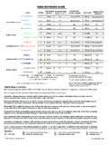
5 No change to Oct 31: Deleted sectionZero tolerance Applied Without MMC2010 Jun 01: Added Implied 90 subsection. Moved the zero positional tolerance section to theAppendix, and wrote the Positional tolerance from First Principles Jun 02: A couple of minor Jul 04: Corrected Figure 52015 Jan 02: Corrected Figure 6 and Figure 7 Finally ran spellcheck. Only two corrections! :)2016 Apr 23: Fixed four bolt pattern equation. Clarified equations for Datum dimensioning Addeda figure for Datum MODELLINGC2 DBOLTDHOLEC2 DHOLECN ominal PositionFigure 1: Bolted Connection worst case2 ModellingWhen parts are held together by more than one fastener, the Tolerances for the holes must ensurenot only that the parts are located to within specification, but also that all the fasteners can beinstalled.
6 Analysis will consist of determining the maximum possible location error that will allowthis, and then working out the equivalent drawing tolerance . It will be assumed that all holesare drilled, punched, tapped or whatever, prior to assembly. If the Tolerances generated by thefollowing calculations are not reasonable, drilling at assembly may be the only analysis will cover a series of fastener configurations and dimensioning procedures. For thepurposes of building analysis models, fastener assemblies can be split up into two categories, whichwill be termed here bolts and screws. For each of these, we can determine a maximum ac-ceptable error, and for each design configuration, and for each style of tolerance application on thedrawing, we can work out the BoltsFasteners pass through clearance holes in both parts.
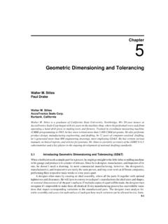
7 The obvious example of this is a nut and boltassembly, but this could also be a cotter pin assembly or a pre-drilled rivet assembly. The boltscould be clamping more than two parts at a Figure 1 . It will be assumed for analysis purposes, that bolts are located precisely at theirnominal position. The two clearance holes are shifted off the nominal position such that their edgesjust touch the bolt, on opposite sides. This is the maximum acceptable error condition. If theclearance in each hole at MMC isc, then.. Screws3 DHOLEC4 DSCREWCN ominal PositionFigure 2: Screwed Connection worst caseMaximum allowable shift of holes for bolting: b=c2(1) ScrewsFasteners pass through a clearance hole in one part, and are solidly located in the other part.
8 Thesecould be screws sitting in tapped holes, or they could be dowel pins, or features integral to one ofthe parts. As with a bolted assembly, a screw could be holding more than one piece to its Figure 2 . The screw and clearance hole have moved in opposite directions, such that thescrew is touching the edge of the hole. Ifcis the clearance in each hole at MMC, then..Maximum allowable shift of holes for screwing: s=c4(2)A screw assembly allows only half the error of a bolted assembly. This is something to consider ifthe location Tolerances are difficult to Positional ErrorThe asme standard recommends the use of positional Tolerances for locating features ofsize, with a secondary preference for profile Tolerances .
9 Much of this article looks at tolerancesfor locating holes. This was the original purpose of the article. People still use this notation fortolerances, and it is defined under the asme standard, so as design checker, you can accept it if it43 FASTENER CONFIGURATIONS works. If you are designing or drafting, you will see from this article that positional Tolerances arethe better two dimensional configurations, it will usually be assumed that the maximum error occurs at a45 angle. The assumption is that the fabricator s capability is equal in both this assumption isnottrue for a given application, then the angle, and the resultant calculationsand Tolerances can be fudged a bit, although, not very Fastener ConfigurationsThe tolerance that must be applied on a drawing feature depends on the configuration of thefasteners and on the dimensioning procedure.
10 Most articles onASME dimensioning andTolerancingpoint out that GD&T provides a maximum of allowance for a given part. This isimportant if the tolerance to be achieved is difficult, and if an increase in allowance can reducecosts. If Tolerances are fairly easy, then the cost of preparing and reading the drawings must beconsidered. Regardless of how the Tolerances are applied, GD&T provides a precise interpretationof how the Tolerances are to be determined from the Implied90 Angles (Warning, Warning, Warning!)See Figure 3 . asme paragraph that undimensioned angles that appearto be 90 are to be assumed to be 90 . The tolerance of an undimensioned orthogonal feature isthe value specified on your default tolerance notes.