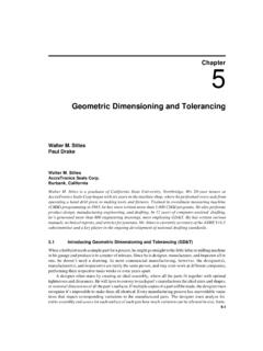
Transcription of Geometric Dimensioning and Tolerancing
1 Geometric Dimensioning and Tolerancing Geometric Dimensioning and Tolerancing (GDT) is o a method of defining parts based on how they function, using standard asme /ANSI symbols; o a system of specifying certain types of dimensions and tolerances. GDT is a combination of symbols and characters that supplements conventional dimensions and tolerances. Both systems GDT and conventional are used on the same drawing. An example comparing conventional Tolerancing to GDT, for a surface that must be round, is shown below 1 Another example of comparison between conventional Tolerancing and GDT for specifying a surface that must be perpendicular: 2 All dimensions and tolerances that are shown on a print must be maintained.
2 Parts that are made to the following figure must conform to both the conventional tolerances as well as the GDT tolerances: Geometric Dimensioning and Tolerancing is used as a supplement to conventional Dimensioning and Tolerancing . 3 When should be used GDT? Example: a table height from the floor to the top is given as 30 inches: Size tolerances alone are sometimes not enough to meet the design needs of a part. Relationships between features may also need to be controlled. 9 Is the top of the table flat? It is, if the tolerance on the 30-inch height is, say, 1 inch.
3 The top could never be more than 31 inches or less than 29 inches. This means that the top must be flat within 2 inches. 9 If the top must be flatter than that, a tighter tolerance might be, say, 1/4 inch. Now the top would be flat to within 1/2 inch. However, the height tolerance becomes too restrictive, causing the rejection of any table that is out of the height tolerance range, even if it is a good table. We need two independent tolerances for these two features! This is an example of trying to control the form of a part with a size tolerance.
4 4 Without GDT, the only way to separate the height tolerance from the flatness tolerance is with notes. The note for the table could read something like this: NOTE 1. TABLE TOP TO BE FLAT WITHIN INCH TOTAL. Using GDT, we could o return to the 1 inch tolerance for the height and o simply place a flatness control (total of .50 inch, in this example) on the top surface. This would solve the problem and would communicate the design needs to the manufacturer and the inspector. The symbols used in GDT create manufacturing and inspection definitions with a minimum of confusion and misinterpretation.
5 The questions that should be asked continuously during the design phase are: What kind of part would be rejected with these tolerances? Will the rejected parts be unusable? Will we reject all of the parts we cannot use? For our table example, the answers are as follows: 1. Any table that is too high or too low (over 31 inches or under 29 inches), even if the top is perfectly flat. What good is a perfectly flat table if it is only 4 inches off the floor? 2. Any table for which the top is not flat enough, even if the table is within height limits.
6 What good is a 30-inch table if the top is too wavy to set a cup of coffee on it? 5 GDT Symbols At the heart of GDT is a rectangular box, the feature control frame, where the Tolerancing information is placed. In the figure of the table example, the feature control frame is divided approximately in half. On the left side is the symbol for flatness, which states the actual Geometric control for the table top. On the right side is the total size of the tolerance zone. In this case, the tolerance zone is inch total. Other examples of feature control frames: The left example defines the parallelism between two surfaces, the right one shows the circularity.
7 6 Different GDT symbols for specifying compact requirements: 7 GDT Rule 1 Geometrics is the part of Tolerancing that has to do with the shapes and positions of features. All dimensions include Geometric controls, whether or not Geometric Tolerancing symbols are used. This idea has been formulated in the Rule 1: Where only a tolerance of size is specified, the limits of size of an individual feature prescribe simultaneously the extent to which variations in its Geometric form, as well as size, are allowed. In other words: Size tolerance by default includes Geometric tolerance of the same feature with the same values.
8 For example, if a shaft is dimensioned as inch in diameter, this controls the circularity of the shaft: In this case the circularity control is the equivalent of 8 In addition, if the shaft drawing is fully dimensioned the following Geometric controls would be required under Rule 1: 1. Straightness of the line elements of the cylinder. The line elements of the cylinder cannot be more bent than the total size tolerance. 2. Flatness of the ends of the shaft. 3. Parallelism between any two opposite line elements. The line elements of the cylinder must not only be straight, they must also be parallel to one another, within the size tolerance of the cylinder.
9 9 The key element is as follows: All dimensions have built-in (natural) Geometric control. Additional symbols should only be used when these natural controls must be refined. For example, in the following figure the roundness of the shaft is controlled first by the diameter tolerance: If the roundness control were removed, the shaft would still have to be round within the limits of the diameter tolerance, per Rule 1. 10 Maximum Material Condition From the size Tolerancing we know that Maximum material condition (MMC) is the condition in which: An external feature, like a shaft, is its largest allowable size.
10 An internal feature, like a hole, is its smallest allowable size. Taken together, it means that the part will weigh its maximum. There are three symbols in GDT relating to material conditions: 1. M - Maximum material condition. 2. L - Least material condition. This is the opposite of MMC (the part will weigh its minimum). 3. S - Regardless of feature size (RFS). This indicates the material condition is not to be considered. This is used where a tolerance is specified and the actual size of the controlled feature is not considered when applying a tolerance.