Transcription of Calculation methods – conveyor belts
1 conveyor and processing beltsCalculation methods conveyor beltsContent1 Terminology2 Unit goods conveying systems3 Take-up range for load-dependent take-up systems8 Bulk goods conveying systems9 Calculation exampleUnit goods conveying systems 12 conveyor and power transmission beltsmade of modern syntheticsWorldwide leaders in technology, quality and serviceFurther information on machine designcan be found in our brochure no. 305 Recommendations for machine design .The formulae, figures and recommenda-tions in this brochure are state of the artand a result of our years of experience. The Calculation results can however differfrom our Calculation programme B_Rex(free download on the internet ). These differences are a result of thebasically different approaches: whereasB_Rex is based on empirical measurementsand requires a detailed description of themachine, the Calculation methods here arebased on general, simple physical formulaeand derivations backed up by factors (c2)that include a safety margin.
2 In the majorityof cases the safety margin used for calcu-lation in this brochure will be larger thanfor the corresponding B_Rex Calculation . Force on each belt strandFNMaximum belt pull (at drive drum)F1 NMinimum belt pull (at drive drum)F2 NEffective belt pullFUNS haft load at drive drumFWANS haft load at end drumFWUNM otor powerPMkWCalculated power at drive drumPAkWBelt pull at 1% elongation per unit of widthSDN/mmDrum/roller widthbmmBelt widthb0mmGeometric belt lengthLgmmCalculation Drum/roller diameterdmmDrive drum diameterdAmmRolling resistance of support rollersf Difference in drum radii hmmCoefficient of friction with support rollers R Coefficient of friction with accumulated goods ST Coefficient of friction with skid plate T Acceleration due to gravityg9,81m/s2 Production toleranceTol%Upper support roller pitchlommLower support roller pitchlummTransition lengthlsmmMass of material conveyed over whole conveying length (total load)
3 MkgMass of beltmBkgMass of all rotating drum/rollers, except drive drummRkgMass of conveyed goods on upper side (total load)m1kgMass of conveyed goods on return side (total load)m2kgMass of conveyed goods per m of conveying length on upper sidem'okg/mLine loadMass of conveyed goods per m of conveying length on return sideLine loadm'ukg/mTension take-up rangeZmmTotal tension take-up rangeXmmHeight of lifthTmConveyor lengthlT belt speedvm/sBelt sagyBmmDrum deflectionyTrmmArc of contact at drive drum and idler Opening angle at drive drum Incline (+) or decline ( ) angle of conveyor , Elongation at fitting %Drive efficiency Density of material conveyed skg/m3 UnitSymbolDesignationTerminology2 conveyor and processing beltsmBmBFU= (m+ ___)+ (___+mR)[N]22FU=please inquire[N]mBmB( )FU= (m+___)+ (___+mR)+ 22( )FU= (m + mB+ mR) + g.
4 M .sin [N]( ) increasing(+) decreasingFU= please inquireFUges= FU1+ FU2+ FU3[N]mBmBFU= (m+___)+ (___+mR)+ [N]2 2FU= (m1+ m2+mB)[N]Coefficient of friction of end drum was ignoredm = of conveyed material per mFU= .(m + mB+ mR)[N] conveyor and processing belts3 Unit goods conveying systemsLoading examples to determinethe effective pull FU [N][N]F1___ c2b04 Coefficients of friction S (guidelines)Maximum belt pull F1c1 constant (is valid for drive drum)c2 constant Counter-checking the type selection0, A0, E0, NOVOU1, V1, VHUH, V2H, U2H,T, U0, PV5H, V10H T (skid plate) R (rollers) ST (*) , V5, U2,V1, U1, UH, U2H0, U0, NOVO, with underside o fA5, E3V2H, V5HT, PArc of contact 180 210 240 180 210 240 180 210 240 smooth steel not recommendablelagged the value___> c2, b0the next stronger type must be : With perforated belts the number of holes reducing the cross-section must be deducted from b0.
5 In the case ofextreme temperatures c2constants change. Please 2/2 E 4/2 NOVO E12/3 TypeE 3/1 E 5/2E 8/2 E12/2E 2/1 E 3/2 E 4/1E 6/1 E10/M E15/M E18/3 E20/M E30/3 E44/3 Constantc2210 58815 25 35 40 60 70F1= FU. c1[N]PM.. _____[N]vIf effective belt pull FUcannot becalculated, maximum belt pull F1can bedetermined from the installed motorpower PMas per the given formula andused to select a belt calculable effective pull and processing belts * accumulated goods5c3 constant (is valid for drive drum)Power PA at drive drumMotor power PM requiredTransilonV3, V5, U2,V1, U1, UH0, U0, NOVO, with underside o fA5, E3T, Psmooth steel drumdry255080wet50not recommendable not recommendablelagged _____[mm]b0.
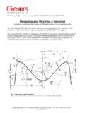
6 Minimum drive drum diameter dAPAPM= ____[kW] = next largest standard motor is chosen _____[kW]1000 conveyor and processing belts6 Take-up range for screw-operated take-up systemsGuidelines for shaft load at rest with force F Tol+Tol zxThe following factors must be taken intoaccount when determining the tensiontake-up range:1. The approximate amount of elongation of the belt resulting from belt determination of see pages 7 and The production length tolerances of the belt (Tol).3. Possible external influences, , stop-and-go operation,which may necessitate a higherelongation (tension) than normal or justify the allowance of a tension take-up , depending on the load, anelongation at fitting in the range of 1% is adequate; a tension take-uprange x of 1% of the belt length is assessing shaft loads please take into account the differing belt pulls instationary and operational for elongation at fitting with head drivesThe minimum operational elongation atthe fitting for a head drive isConveyor at restFW1=FW2=2.
7 FF % . [N]FU/2 + _____[%] 2 . drive in operationF2= F1 FUFWA= F1+ F2 conveyor and processing belts7 Guidelines for elongation at fitting with tail drivesThe operational elongation at fitting for ahead drive isGuidelines for elongation at fitting with return-side drivesGuidelines for operational shaft loadThe operational elongation at fitting for areturn-side drive isFU/2 + + FU _____[%] 2 . (c1 K) _____[%]SD .boTail drive in operationF2= F1 FUFW3FW6 Return side drive in operationK with head drive= return-side drive = trail drive= snub roller = 15 _____FW3= 2 .F12 2 . [N]Example snub roller = 25 _____FW6= 2 .F22 2 . [N]Example drive drum = 180 FWA= F1+ F2 conveyor and processing belts8 Determination of FRExample for determining the tensioningweight FR[N] with a 180 arc of contact.
8 FR=2 .F2 FTR[N]Example for determining the tensioningweight FR[N] with an angle as weight of tension roller [N] FR= 2 F2 cos __ _FTR[N]2 With gravity-operated take-up systems thetensioning weight must generate the forceF2in order to achieve satisfactory grip bythe belt on the drive drum (spring-loaded,pneumatic and hydraulic take-up devicesoperate in similar fashion).The tensioning weight must be capable ofmoving freely. The take-up unit can onlybe installed after the drive unit. Such adesign cannot be used with a take-up range is a function of theeffective pull, the required force F2, the beltlength Lg, its delivery tolerance Tol, thetension reserve Z and the belt range forload-dependent take-up systemsFUF1F2F2 FTRFRFUF1F2F2 FTR FRConveyor and processing beltsConveyor and processing belts9 Longitudinal angle of incline Density of certain bulk goodsVolume flow for flat conveyorsBulk goods conveying systemsBulk goods (ca.)
9 Ash, dry16 Ash, wet18 Earth, moist18 20 Grain, except oats14 Lime, lumps15 Potatoes12 Gypsum, pulverized23 Gypsum, broken18 Wood, chips22 24 Fertilizer, artificial12 15 Flour15 18 GoodsBulk density [103kg/m3]Ash, cold, , , except , , , , lumps , , , , goods (ca. )Salt, fine15 18 Salt, rock18 20 Loam, moist18 20 Sand, dry, wet16 22 Peat16 Sugar, refined20 Sugar, raw15 Cement15 20 GoodsBulk density [103kg/m3]Gypsum, , , , , , , , for maximum incline angles for various bulk values are determined by the particleshape, size and mechanical properties ofthe material conveyed, irrespective of thesurface material of the table shows the hourly volume flow(m3/h)
10 At a belt speed of v = 1 m/s for a flat,horizontal conveyor belt with 20 mm highT20 longitudinal profiles welded alongboth edges of the top 1400 Angle of surcharge 0 25 3242 52 66 80 94 Angle of surcharge 10 40 5788 123 181 248 326 conveyor and processing belts10b0mm40050065080010001200 140020 troughedAngle of surcharge 0 21 3667 105 173 253 355 Angle of surcharge 10 36 60 110 172 281 412 57230 troughedAngle of surcharge 0 30 5195 149 246 360 504 Angle of surcharge 10 44 74 135 211 345 505 703 Note: In practical operations the theore-tical value established for the volume flowis seldom obtained since it applies only to belts running horizontally and loadedevenly.