Transcription of CALIBRATION OF TAPE MEASURES WITH SMALL …
1 DAAAM INTERNATIONAL SCIENTIFIC BOOK 2012 pp. 187-196 CHAPTER 16. CALIBRATION OF tape MEASURES with SMALL . MEASUREMENT UNCERTAINTY. GODINA, A. & ACKO, B. Abstract: tape MEASURES are probably the most wildly used length measuring instruments in the world. The MEASURES , used by surveyors, contractors and other professionals in building and construction industry, measurements of land areas, legal investigations etc. have to be calibrated and for legal purposes verified, to ensure traceability and avoid various controversies, misalignments and other problems. In the paper the precise CALIBRATION procedure is presented. In spite of extremely SMALL measurement bench with the length of only three metres, by the use of precise measurement equipment (laser interferometer and video system) and thorough uncertainty evaluation based on experimental and theoretical work, very SMALL CALIBRATION uncertainty is achieved.
2 The procedure was successfully accredited and accepted as CALIBRATION and measurement capability (CMC) into key comparison database at BIPM. Key words: tape measure , CALIBRATION , measurement, uncertainty Authors data: Dr. Sc. Godina, A[ndrej]; Dr. Sc. Acko, B[ojan], University of Maribor, Faculty of mechanical engineering, Smetanova 17, SI-2000 Maribor, Slovenia, This Publication has to be referred as: Godina, A[ndrej] & Acko, B[ojan] (2012). CALIBRATION of tape MEASURES with SMALL Measurement Uncertainty, Chapter 16 in DAAAM International Scientific Book 2012, pp. 187-196, B. Katalinic (Ed.), Published by DAAAM International, ISBN 978-3-901509-86-5, ISSN 1726-9687, Vienna, Austria DOI: 187. Godina, A. & Acko, B.: CALIBRATION of tape MEASURES with SMALL Measurement U . 1. Introduction Among other, more precise length measuring instruments, most length CALIBRATION laboratories also perform tape MEASURES calibrations.
3 Usually long measurement benches, build specially for this purpose, are used for the task. Its length ranging in from several metres up to 30 m, modern measurement bench is equipped with linear position encoder and cart with a positioning system. Positioning systems differ largely, starting from simple magnifying glass over optical microscope to enhanced video systems with line recognition. For a SMALL CALIBRATION laboratory purchase of a special tape CALIBRATION bench was not economically viable, so we adapted our length measuring device Zeiss ULM. 3000. The ULM was equipped with existent laser interferometer, video probing system (VPS) and fixtures for tapes and weights. 2. CALIBRATION procedure Application and limitations of the procedure tape MEASURES , in legal documents called "material MEASURES of length" (in the following text " MEASURES "), are simple instruments comprising scale-marks whose distances are given in legal units of length.
4 They can be used in legal and non-legal metrology. The procedure concerns different kinds of MEASURES , as defined by the Measuring instruments directive (MID, 2004). Steps taken when calibrating MEASURES up to 200 m will be described. Different designs of MEASURES influence the way of fixing the measure for the CALIBRATION . Tractive force for loading the MEASURES during CALIBRATION is for some MEASURES stated on the measure , for all others it is prescribed by MID. This procedure and its uncertainty is limited for the use of the LI, but no major changes are needed when using CALIBRATION bench with an encoder. Pre- CALIBRATION tasks Prior to CALIBRATION , measure has to be visually checked for any obvious defects like scratches or other defects ( corrosion), which would impede the CALIBRATION . measure is cleaned with alcohol and checked, if graduation and numbering is complete, readable and undeletable.
5 Temperature stabilisation at 20 C 0,5 C is performed for minimum of six hours. Fixation of the measure The measure is fixed in accordance with the kind of the measure in a special fixture. The MEASURES differ substantially at the end and can be divided in three groups: MEASURES with end hook, ring or handle;. MEASURES with floating tang (for both inside and outside dimensions measurement);. Dipping tapes with sinkers. 188. DAAAM INTERNATIONAL SCIENTIFIC BOOK 2012 pp. 187-196 CHAPTER 16. While at the measure with a floating tang or a sinker a measurement is bounded by a tang's surface or sinker's tip, scale at the measure with end hook starts several centimetres after the hook. Fixing of this end of the measure must be carried out accordingly to the measure end; special fixtures are needed. Because of the bench length of only 3 m, MEASURES longer than 3 m are measured in more steps.
6 In the second and in the following steps the measure is fixed with clamps. On the free hanging end the measure is loaded with a weight that corresponds to the specified tractive force. If tractive force is not specified by manufacturer and marked on the tape , for MEASURES of 5 m and longer MID prescribes the tractive force of 50 N. The tractive force is established by the fixing of the weight on the loose end of the measure . Dipping tapes with sinkers are loaded with a weight, that equals the sinker's mass (normally 0,5 kg or 1 kg). Adjusting the measure Before measurement the measure shall be adjusted parallel to the axis of measurement. The adjustment is performed using the horizontal (x) axis of the coordinate cross of VPS. The upper line of the double cross is positioned on the top of the reference mark of the measure . After that the VPS is positioned to the end mark of the measure .
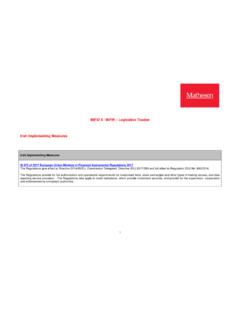
7 It is checked whether the line is touching the top of the mark on the measure . If this is not the case, the measure is moved slightly until the cross line touches the top of the mark. The procedure is repeated so until the cross touches both marks (reference and the end mark) on the top. Measurement Distances between the zero- mark and 10 to 30 random scale-marks including the end- mark are measured. The number of measuring points depends on the length of the scale. The positioning system is always set to the axis of a mark as shown in Figure 5 using double co-ordinate cross. The light slots on both sides of the line shall be equal. Fig. 1. Position of the co-ordinate cross when measuring distances between scale marks If the zero point is defined by an end surface, the reference scale-mark for the measurement (scale-mark from which distances are measured) is the closest mark indicating a round measure ( 10 mm, 50 mm, etc.)
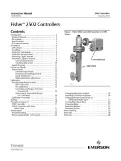
8 , depending on the type of the measure ). 189. Godina, A. & Acko, B.: CALIBRATION of tape MEASURES with SMALL Measurement U . Measured values are recorded by LI software and copied into Excel file for final calculations, after the measurement is completed. 3. Correction of the measurement result Correction of the measure 's thermal extension Temperature of the measure is measured on the base plate in two points using the material temperature contact sensors of LI. LI's software carries out on-line correction of thermal extension. Correction of Abbe error The angle between the guide on the bench and the cart carrying VPS and LI. optics was measured by electronic level. Two levels were positioned as shown in Fig. 4, first fixed on the guide, while second was on the cart that was moved along the whole length of the bench. Maximum Abbe error, caused by the pitch of the cart, was calculated and the value taken into the uncertainty evaluation.
9 Fig. 2. Measurement of the pitch angle of the cart carrying VPS and LI optics 4. Measurement uncertainty Mathematical model of measurement Deviation e (measurement result) is given by the expression (Acko, 2012): e = Lm (1+ m m) - LLI + ecos + emp + ea eF (1). where: e - deviation (measurement result) at 20 C. Lm - path length between the reference position of the video probing system and the measurement position of the video probing system m - linear temperature expansion coefficient of material measure of length m - temperature deviation of the measure of length from 20 C. 190. DAAAM INTERNATIONAL SCIENTIFIC BOOK 2012 pp. 187-196 CHAPTER 16. LLI - corrected length shown by LI. ecos - cosine error of measurement (supposed to be 0). emp - dead path error (supposed to be 0). ea - Abbe error caused by angular deviation of the video probing system (supposed to be 0).
10 EF - error due to the tractive force Standard uncertainties of the estimations of the input values Equation ( ) in (EA-4/02, 1999) in our case gets the following form: uc2(e) = cLm2u2(Lm) + c m2u2( m) + c m2u2( m) + cLLI2u2(LLI) + (2). + cecos2u2(ecos) + cemp2u2(emp) + cea2u2(ea) + ceF2u2(eF). ci are partial derivatives of the function (1): c Lm = f/ Lm = 1+ m m 1; if max= 1 C (3). c m = f/ m = m Lm (4). c m = f/ e = m Lm (5). c LLI = f/ LLI = -1 (6). cecos = f/ ecos = 1 (7). cemp = f/ emp = 1 (8). cea = f/ ea = 1 (9). ceF = f/ eF = 1 (10). Standard uncertainties of influence (input) values are calculated (estimated) for applied equipment and method as well as for supposed measurement conditions. Uncertainty of the path length between the reference position of the video probing system and the measurement position of the video probing system u2(lm). The uncertainty is composed of the positioning uncertainty in the reference point u(posref) and of the positioning uncertainty in the measurement point u(posmea).