Transcription of Fisher 2502 Controllers - Emerson
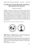
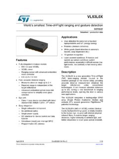
1 2502 of Sensor Caged Cageless Mounted Mounted Set Band Relief and Torque Tube Suspended Weightfor of controller with ResetRelief controller from CONTROLLER249B SENSORW8334 Figure 1. Fisher 2502 controller Mounted on 249 BSensorChanging Mounting controller on Proportional, Reset, orDifferential Relief Relay Dead ManualD200126X0122502 ControllersSeptember 2019 Instruction ManualD200126X0122502 ControllersSeptember 20192 IntroductionScope of ManualThis instruction manual provides installation, operating, calibration , and maintenance procedures for Fisher 2502pneumatic Controllers (figure 1) used in combination with Fisher 249 level manual does not include regulator or sensor installation or maintenance procedures.
2 For this information, refer tothe instruction manual for the appropriate regulator and 249 level not install, operate, or maintain a 2502 controller without being fully trained and qualified in valve, actuator, andaccessory installation, operation, and maintenance. To avoid personal injury or property damage, it is important tocarefully read, understand, and follow all contents of this quick start guide, including all safety cautions and you have any questions about these instructions, contact your Emerson sales office before 2502 controller described in this manual provides proportional plus reset and proportional plus reset withdifferential relief valve control.
3 The controller output is a pneumatic signal that operates a final control element. Thesecontrollers are designed to control liquid level, the level of interface between two liquids, or density (specific gravity).Each unit consists of a 249 liquid level sensor and a 2502 pneumatic to the Principle of Operation section for a more comprehensive discussion of how the 2502 pneumatic 1 gives general specifications for 2502 ServicesFor information on available courses for the 2502 controller , as well as a variety of other products, contact: Emerson Automation SolutionsEducational Services - RegistrationPhone: 1-641-754-3771 or 1-800-338-8158E-mail: ManualD200126X0122502 ControllersSeptember 20193 Table 1.
4 SpecificationsAvailable Configurations2502: A direct acting controller which providesproportional plus reset control2502C: A 2502 with a level indicator assembly2502F: A 2502 with a differential relief valveThese products are also available with reverse example, 2502R, 2502CR, and 2502 FRInput SignalLiquid Level or Liquid to Liquid Interface Level: From0 to 100 percent of displacer length standardlengths for all sensors are 356 mm (14 inches) or 813mm (32 inches). Other lengths available dependingon sensor constructionLiquid Density: From 0 to 100 percent ofdisplacement force change obtained with givendisplacer volume standard volumes are 980 cm3 (60inches3) for 249C and 249CP sensors, or 1640 cm3(100 inches3) for most other 249 sensors.
5 Othervolumes available depending on constructionOutput to bar (3 to 15 psig) or to bar (6 to 30 psig)Action: Field reversible between direct (increasingliquid or interface level or specific gravity increasesoutput pressure) and reverse (increasing liquid orinterface level or specific gravity decreases outputpressure)Area Ratio of Relay Diaphragms3:1 Supply MediumAir or Natural GasSupply medium must be clean, dry, and noncorrosivePer ISA Standard maximum 40 micrometer particle size in the airsystem is acceptable. Further filtration down to 5micrometer particle size is recommended. Lubricantcontent is not to exceed 1 ppm weight (w/w) orvolume (v/v) basis.
6 Condensation in the air supplyshould be minimizedPer ISO 8573-1 Maximum particle density size: Class 7 Oil content: Class 3 Pressure Dew Point: Class 3 or at least 10_C less thanthe lowest ambient temperature expectedSupply Pressure bar(1) (20 psig) for to bar (3 to 15 psig)output signal or bar(1) (35 psig) for to bar(6 to 30 psig) output signalMaximum Supply Pressure(2) bar (50 psig)Supply Pressure Consumption(3)At bar (20 Psig)Minimum: normal m3/h ( scfh) at proportionalband setting of 0 or 200 percentMaximum: normal m3/h (27 scfh) at proportionalband setting of 100 percentAt bar (35 psig)Minimum: normal m3/h (7 scfh) at proportionalband setting of 0 or 200 percentMaximum: normal m3/h (42 scfh) at proportionalband setting of 100 percentPerformanceHysteresis: percent of output pressure change at100 percent of proportional bandRepeatability: percent of displacer length ordisplacement force changeDead Band: percent of proportional band orspanTypical Frequency Response.
7 4 Hz and 90 degreephase shift at 100 percent of proportional band withoutput piped to typical instrument bellows using (20 feet) of mm (1/4 inch) tubingAmbient Temperature Error: $ percent of outputpressure change per 50_F (28_C) of temperaturechange at 100 percent of proportional band whenusing sensor with standard wall N05500 torque tubewith 249 sensorsReset: Adjustable from to 74 minutes per repeat(100 to repeats per minute)Differential Relief (2502F and 2502FR ControllersOnly): Adjustable from to bar differential (2to 7 psi) to relieve excessive difference betweenproportional and reset pressures.
8 Differential reliefcan be switched between rising output pressure andfalling output Tubing Connections1/4 NPT internalMaximum Working Pressures (Sensors Only)Consistent with applicable ASME pressure/temperature ratings(continued)Instruction ManualD200126X0122502 ControllersSeptember 20194 Table 1. Specifications (continued)Hazardous Area Classification2502 Controllers comply with the requirements ofATEX Group II Category 2 Gas and DustEx h IIC Tx GbEx h IIIC Tx DbMaximum surface temperature (Tx) depends onoperating conditionsGas: T4, T5, T6 Dust: Ambient Temperatures(2)Standard Construction: -40 to 71_C (-40 to 160_F) High Temperature Construction: -18 to 104_C (0 to220_F)See figure 2 Declaration of SEPF isher Controls International LLC declares thisproduct to be in compliance with Article 4 paragraph3 of the PED Directive 2014/68/EU.
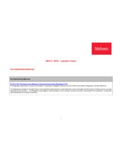
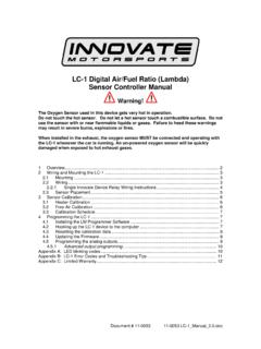
9 It was designedand manufactured in accordance with SoundEngineering Practice (SEP) and cannot bear the CEmarking related to PED , the product may bear the CE marking toindicate compliance with other applicable EuropeanCommunity : Specialized instrument terms are defined in ANSI/ISA Standard - Process Instrument Control and stability may be impaired if this pressure is The pressure/temperature limits in this document, and any applicable standard or code limitation should not be Normal cubic meters per hour (m3/hr) at 0_C and bar. Scfh=standard cubic feet per hour at 60_F and psia .Figure 2.
10 Guidelines for Use of Optional Heat Insulator AssemblyUSE INSULATOR (CAUTION! IF AMBIENT DEWPOINT IS ABOVEPROCESS TEMPERATURE, ICE FORMATION MAY CAUSE INSTRUMENTMALFUNCTION AND REDUCE INSULATOR EFFECTIVENESS.)0204060801001201401600102 0-18-10304050607071593500400300200100004 008001100-20-29NO INSULATOR NECESSARYAMBIENT TEMPERATURE(_C)STANDARD controller OR TRANSMITTERAMBIENT TEMPERATURE (_F)HEAT INSULATORREQUIREDTOOHOTNOTE: FOR SERVICE BELOW -29_C (-20_F) CONTACT TEMPERATURE ( C)_PROCESS TEMPERATURE ( F)_B1413 102040608010012014020001020-18-103040506 07093593500400300200100004008001100-20-2 9NO INSULATOR NECESSARYAMBIENT TEMPERATURE (_C)HIGH TEMPERATURE controller OR TRANSMITTERAMBIENT TEMPERATURE (_F)HEAT INSULATORREQUIREDTOOHOTPROCESS TEMPERATURE ( F)_1801608090 USE INSULATOR (CAUTION!)