Transcription of Manual: 99 Pressure Reducing Regulator
1 Type 99D100260X012 Instruction ManualForm 589 February 99 Pressure Reducing RegulatorIntroductionScope of the ManualThis manual describes and provides instructions for installation, startup, adjustment and parts ordering information of Type 99 Pressure Reducing Regulator complete with standard P590 Series integral fi lter. Information on other equipment used with this Regulator can be found in separate 1. Type 99 Regulator with Type 61H (High Pressure ) PilotW2676!WARNINgSince a pilot-operated Regulator is constructed of both a pilot and a main valve, care should be used not to exceed the maximum inlet Pressure shown on the nameplate of either unit. When inlet Pressure exceeds the pilot limitation, a pilot supply Reducing Regulator and/or relief valve is required.!WARNINgFailure to follow these instructions or to properly install and maintain this equipment could result in an explosion and/or fi re causing property damage and personal injury or death.
2 Fisher regulators must be installed, operated and maintained in accordance with federal, state and local codes, rules and regulations and Emerson Process Management Regulator Technologies, Inc. instructions. If the Regulator vents gas or a leak develops in the system, service to the unit may be required. Failure to correct trouble could result in a hazardous condition. Call a gas service person to service the unit. Only a qualifi ed person must install or service the Regulator . Type 992 DescriptionThe Type 99 gas Regulator provides a broad capacity for controlled Pressure ranges and capacities in a wide variety of distribution, industrial and commercial Type 99 Regulator has a Type 61L, 61LE or 61LD (low Pressure ); Type 61H (high Pressure ); or Type 61HP (extra high Pressure ) pilot integrally mounted to the actuator casing as shown in Figure 1. The Type 99 Regulator can handle up to 1000 psig / bar inlet Pressure (the 1000 psig / bar Regulator requires a Type 1301F pilot supply Regulator and a Type H110 pop relief valve).
3 The pilot supply Regulator reduces inlet Pressure to a usable 200 psig / 14 bar for the extra high- Pressure pilot. The standard Type 99 Regulator comes with O-ring seals on the guide bushing and valve carrier to keep main valve body outlet Pressure from interfering with outlet Pressure in the lower casing and ratings for various Type 99 constructions are listed in the Specifications section below. Some specifications for a given Regulator as it originally comes from the factory are stamped on the nameplates located on the pilot and actuator spring cases. An additional nameplate may be installed on the pilot to indicate a Regulator with O-ring stem seal. These regulators and their installations should be checked for compliance with applicable codes. 1. The Pressure /temperature limits in this Instruction Manual and any applicable standard or code limitation should not be exceeded. 2. For stability or overpressure protection, a pilot supply Regulator may be installed in the pilot supply tubing between the main valve and Constructions Type 99L - Type 99 with Type 61L pilot which has 2 in.
4 To 20 psig / 5 mbar to bar Pressure range Type 99LD - Type 99 with Type 61LD pilot which has a narrower proportional band than the standard Type 61L pilot Type 99LE - Type 99 with Type 61LE pilot which has a broader proportional band than the standard Type 61L pilot Type 99H - Type 99 with Type 61H pilot which has 10 to 65 psig / to bar Pressure range Type 99HP - Type 99 with Type 61HP pilot has 35 to 100 psig / to bar Pressure rangeBody Size and End Connection StylesNPS 2 / DN 50 body with NPT, CL125 FF, CL150 RF, CL250 RF and CL300 RF end connectionsMaximum Allowable Inlet Pressure (1)160 psig / bar: Type 61LD pilot400 psig / bar: Type 61L, 61LE or 61H pilots 1000 psig / bar: Type 61HP pilot, along withType 1301F pilot supply Regulator and Type H110 relief valve (1/2 in. / 13 mm orifice only)Outlet (Control) Pressure Ranges(1)See Table 1 Approximate Proportional BandsSee Table 2 Maximum Allowable Pressure Drop(1)See Table 3 Maximum Actuator Pressures(1)Operating: 100 psig / barEmergency: 110 psig / barMaximum Pilot Spring Case Pressure for Pressure Loading(1)(2)Types 61L, 61LD and 61LE: 50 psi / bar with special steel closing capTypes 61H and 61HP: 100 psi / barMinimum Differential Pressure Required for Full StrokeSee Table 3 Maximum Rated Travel1/4 in.
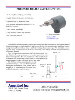
5 / mmTemperature Capabilities(1)With Nitrile (NBR) / Neoprene (CR) / Nylon (PA): -20 to 180 F / -29 to 82 CWith Fluorocarbon (FKM): 0 to 300 F / -18 to 149 CType 993 Figure 2. Schematic of Type 99 Regulator with Type 61L (Low Pressure ) PilotA6814 OuTLET PIPEPILOT ORIFICEBLEED ORIFICEBLEED vALvEPILOT DIAPHRAgM ASSEMBLyPuSHER POST ASSEMBLyMAIN DIAPHRAgMMAIN vALvE SPRINgPILOT CONTROL SPRINgPILOT DIAPHRAgMINLETINLET PRESSuREOuTLET PRESSuREATMOSPHERIC PRESSuRELOADINg PRESSuREPrinciple of OperationThe key to the operation of a Type 99 Regulator is the yoked double-diaphragm pilot. Fast response and accuracy are made possible by the amplifying effect of the Pressure -balanced pilot and by the two-path control system. The function of the pilot is to sense change in the controlled Pressure and amplify it into a larger change in the loading Pressure . Any changes in outlet Pressure act quickly on both the actuator diaphragm and the loading pilot, thus providing the precise Pressure control that is a characteristic of a two-path typical pilot has an approximate gain of 20, which means the outlet Pressure needs to droop only 1/20 as much as a direct-operated Regulator in order to obtain the same Pressure differences across the main diaphragm.
6 Advantages of a pilot-operated Regulator are high accuracy and high capacity. Upstream or inlet Pressure is utilized as the operating medium, which is reduced through pilot operation to load the main diaphragm chamber. Tubing connects the inlet Pressure to the pilot through a filter assembly. Downstream or outlet Pressure registers underneath the main diaphragm through the downstream control operation, assume the outlet Pressure is less than the setting of the pilot control spring. The top side of the pilot diaphragm assembly will have a lower Pressure than the setting of the spring. Spring forces the diaphragm head assembly upward, opening the relay or inlet orifice. Additional loading Pressure is supplied to the pilot body and to the top side of the main creates a higher Pressure on the top side of the main diaphragm than on the bottom side, forcing the diaphragm downward. This motion is transmitted through a lever, which pulls the valve disk open, allowing more gas to flow through the the gas demand in the downstream system has been satisfied, the outlet Pressure increases.
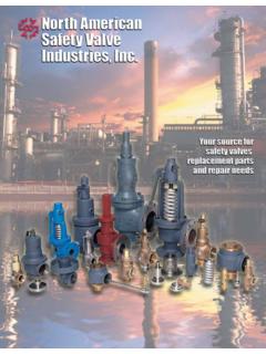
7 The increased Pressure is transmitted through the downstream control line and acts on top of the pilot diaphragm head assembly. This Pressure exceeds the pilot spring setting and forces the head assembly down, closing the orifice. The loading Pressure acting on the main diaphragm bleeds to the downstream system through a small slot between the pilot bleed valve and the bleed 994 Figure 3. Schematic of Type 99 Regulator with Type 61HP (Extra High Pressure ) PilotDOWNSTREAM CONTROL LINEMAIN DIAPHRAgMPuSHER POST ASSEMBLyMAIN vALvE SPRINgFLANgE ADAPTORPILOT DIAPHRAgMINLET Pressure TuBINg CONNECTIONPILOT SPRINgRELIEF vALvE CAPDIAPHRAgMBLEED ORIFICEBLEED vALvERELIEF vALvE BODyyOKE LEgyOKE CAPyOKE CAPRELAy vALvEORIFICE54A2767-aA2505 INLET PRESSuREOuTLET PRESSuREATMOSPHERIC PRESSuRELOADINg PRESSuREPILOT TyPEMAXIMuM PILOTSuPPLy PRESSuREOuTLET (CONTROL) Pressure RANgEPILOT CONTROL SPRINgPart NumberColor CodeWire DiameterFree to 4 in.
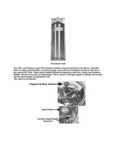
8 (1)3 to 12 in. (1) to 21 to 52 to 105 to 1510 to 205 to 10 mbar(1)7 to 30 mbar(1) to to to to to to 65 to 0Y066427022 Green to 100 to Type 61LD pilot only. Table 1. Outlet Pressure RangesPILOT TyPEPILOT CONTROL SPRINgPROPORTIONAL BANDPart NumberColor CodeWire DiameterFree 105 to to 1 to to 5 to to 2 to to 20 61L, 61LD and to to bar61H0Y066427022 Green to psi to to to barTable 2. Proportional BandsType 995 Figure 4. Working Monitor Installation20A1389-AB2484 DISTRIBuTION Pressure CONTROL LINETyPE 161 AyW MONITORINg PILOT (ALSO REPRESENTATIvE OF TyPE 627-109)PILOT SuPPLy LINEWORKINg MONITOR PILOTINTERMEDIATE PRESSuREINTERMEDIATE Pressure CONTROL LINELOADINg PRESSuREuPSTREAM PRESSuREOPTIONAL PILOT SuPPLy REguLATORWORKINg MONITOR REguLATORWORKINg REguLATOROPTIONAL PILOT SuPPLy REguLATORPILOT SuPPLy PIPINg FOR WORKINg Regulator WHEN PILOT IS REQuIRED TO BE SuPPLIED FROM uPSTREAM PRESSuREDISTRIBuTION Pressure FLEXIBLE ARRANgEMENT THAT PERMITS WIDE-OPEN MONITOR TO BE EITHER uPSTREAM OR DOWNSTREAMF igure 5.
9 Typical Wide-Open Monitor InstallationsMINIMuM PIPINg ARRANgEMENT THAT REQuIRES WIDE-OPEN MONITOR TO ALWAyS BE uPSTREAM10A1386-AA2503uPSTREAM Regulator (REQuIRES O-RINg STEM SEAL)WORKINg REguLATOROPTIONAL PILOT SuPPLy REguLATOR10A1388-AA2504uPSTREAM Regulator (REQuIRES O-RINg STEM SEAL)OPTIONAL PILOT SuPPLy REguLATORType 996 Table 3. Maximum Allowable Pressure Drop and Minimum Differential PressuresTable 4. Orifice SizesMAXIMuM ALLOWABLE Pressure DROPMAIN vALvE SPRINgMINIMuM DIFFERENTIAL Pressure FOR FuLL STROKEDISK MATERIALMAXIMuM ORIFICE SIZE(1)(5)Part NumberWire DiameterFree (NBR), Fluorocarbon (FKM)1-1 (CR), Fluorocarbon (FKM)1-1 (NBR), Neoprene (CR), Fluorocarbon (FKM)1-1/8 29175(2) (2) (NBR), Neoprene (CR), Fluorocarbon (FKM) 7/822250 (NBR), Neoprene (CR), Fluorocarbon (FKM) 7/8 22300 (PA)1-1/8(3)29(3)400 (PA)7/8 221000 (PA)1/2(4)13(4)1. Can use all orifice sizes up to maximum size listed.
10 See Table CL125 FF flanged body 1-1/8 in. / 29 mm is the only orifice available for 300 psig / bar maximum inlet Pressure 1/2 in. / 13 mm is the only orifice available for 1000 psig / bar maximum inlet Pressure O-ring seat construction is only available for 7/8 and 1-1/8 in. / 22 and 29 mm orifice CONSTRuCTIONORIFICE capacity trim, Straight bore Composition or Nylon (PA) disk seat only1/2(1)3/413(1)19 Restricted capacity trim(2), Stepped bore Composition or Nylon (PA) disk seat only7/8 x 3/8 7/8 x 1/2 7/8 x 5/8 22 x 1022 x 1322 x 16 Full capacity trim,Composition or Nylon (PA) disk or O-ring seat7/8 1-1/8 22291. 1/2 in. / 13 mm is the only orifice size available for 1000 psig / bar maximum inlet Pressure Maximum inlet rating is equivalent to the 7/8 in. / 22 mm pilot valve diaphragm acts as a sealing member for the loading chamber and as a balancing member to the upper pilot diaphragm. These two diaphragms are connected by a yoke so any Pressure change in the pilot chamber has little effect on the position of the pilot valve.