Transcription of Cameron Type 31 Welded Body Ball Valve - WEGMAN
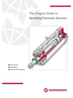
1 PublicationTC1411-ACameronType 31 Welded body ball ValveInstallation, Operation and Maintenance ManualPage 1 of 20 Installation, Operation and Maintenance ManualCameronType 31 Welded BodyBall ValveRPublicationTC1411-ACameronType 31 Welded body ball ValveInstallation, Operation and Maintenance ManualPage 2 of 20 Publication TC1411-A Published August 1999 Cooper Cameron Corporation, Cooper Cameron valves Division, rights 31 Welded body ball ValveInstallation, Operation and Maintenance ManualPage 3 of 20 Table of ContentsPrinciple 31 Welded body ball ValveInstallation, Operation and Maintenance ManualPage 4 of 20 Principle ComponentsFigure 1 - Cooper Cameron valves ' Cameron Welded body ball Valve DESCRIPTION1 Keyed shaft2 Upper stem seal*3 Upper body4 Lower stem seal5 Stem bearing6 Dog7 Ball8 Seat ring9 Lip seal10 End connection11 Lower body12345675891011*Details of stem are on pages 18 and 31 Welded body ball ValveInstallation.
2 Operation and Maintenance ManualPage 5 of 20 Cameron Welded body ball Valve OverviewNameplate InformationITEM STAMP1 Nominal Valve size x actual bore Maximum temperature3 Minimum temperature4 body material symbol5 Seat insert material symbol6 Assembly part number7 Valve length8 API Class designation9 Maximum working pressure10 Maximum operating pressure11 Seat material symbol12 ball material symbol13 Valve assembly serial number14 Month and year of manufactureStorageThe valves are conditioned for a storage period ofapproximately six months.
3 The following careshould be taken when storing sure the Valve end connection coversremain in place during the Valve does not have an operator alreadyinstalled and the Valve will be stored outside,the open stem extension or the stem adaptershould be covered to avoid water of the most trusted valves in the petroleumindustry,Cooper Cameron valves Welded body BallValve combines the strength of forged componentswith a lightweight and compact spherical Welded body ball valves satisfy ANSI 150through 2500 (PN 20 through PN 420) and API 2000through 5000 standards. Made of forged steel toassure uniform fine grain structure and toughness,they may be specified in sizes from 2 to 56 (DN 50 to DN 1400). Engineered for heavy-dutyservice, and minimal maintenance, the CameronWelded body ball Valve is commonly selected for anumber of applications.
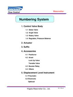
4 The distinctive design ofthe Cameron Welded body ball Valve gives itmaximum strength and minimum weight as wellas maximum resistance both to pipeline pressureand stresses. The compact, spherical design alsoeliminates body flanges, thus reducing overall sizeand leak long-term storage is required, the valveshould be conditioned using a corrosioninhibitor and end connection covers. Followthe guidelines found in Cameron EngineeringBulletin 476B for long term storage. Obtain acopy from your Cooper Cameron 2 - Typical Valve 31 Welded body ball ValveInstallation, Operation and Maintenance ManualPage 6 of 20 InstallationHandling of Valve should be lifted in such a way thatthe body supports the : The journal and the end connec-tion necks are suitable places to attachlifting slings.
5 Never use handwheels orother protruding parts of the gearbox oractuator not designated for this the Valve is equipped with lifting lugs, theseshould be used for end protector covers should be kept inplace on the end connections during allhandling. Remove only during final installa-tion of the : During handling, protect the endconnection faces and fittings againstdamage from the lifting devices. Failure tocover faces and fittings could cause damageto the of ValveThe ball Valve may be installed in any end of the Valve may be installed as theupstream of BallCaution: The ball should be fully openduring the installation of the Valve . Failureto keep the ball fully open during installa-tion could cause damage to the the ball must remain in the closed positionduring installation of the Valve , coat the exposedsurfaces of the ball with grease.
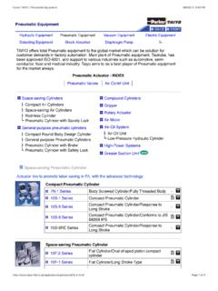
6 This will protectthe plug from damage due to weld : Do not leave the Valve in thepartially open position for an extendedperiod of 4 - Correct lifting using the Valve lifting 3 - Correct Valve lifting using end connection InstructionsWhen preheating, welding or stress relieving, bodytemperatures must not exceed 4000F (2000C) at anypoint beyond 3 (75 mm) from the weld. Usetempil sticks to check Cameron ball valves are Welded into finalposition in the pipeline, cover the Valve seal areas( ball -to-seat area and seat-to-end connection area)with 1 wide masking tape from the 3 o clock tothe 9 o clock position. This will help prevent anyforeign material from becoming lodged in theseareas. The piping system should also be piggedbefore operation or pressure testing to remove anyforeign material from the : A weld end Valve without puppipes should never be installed in theclosed 31 Welded body ball ValveInstallation, Operation and Maintenance ManualPage 7 of 20 Hydrostatic TestingWhen Cameron ball valves are installed in a pipingsystem that requires hydrostatic testing of theadjoining pipe, follow these procedures to mini-mize any damage that could occur to the sealingsurfaces and seat seals inside the should be in the fully open positionwhen the injection of test fluid begins.
7 Thiswill allow any pipeline debris to be flushedthrough the Valve bore and out of the the piping system has been purged ofdebris and the system has been filled com-pletely with the test fluid, the ball valveshould be placed in the partially open position(approximately 10o from the fully open posi-tion). This allows test fluid into the body cavityof the Valve is now ready to be pressure completion of hydrostatic testing, thevalve should be returned to the fully openposition before removing the test fluid fromthe piping system. The test fluid in the bodycavity can be drained through the body drainport located on the lower portion of the the Valve and piping system have beenpigged and customer product is injected intothe piping system, the Valve should be movedto the partially open position (approximately10o from the fully open position).
8 Any remain-ing test fluid trapped in the Valve body cavitycan then be vented through the body bleedplug, located on the lower portion of the valvebody. If the Valve has been fitted with a stemextension, the vent fitting will be locatedbelow the mounting flange on top of the body bleed fitting will forcetrapped test fluid out of the body cavity. Keepthe bleed plug open until all fluids have beenexhausted through the body bleed the Valve body bleed fitting and returnthe Valve to the fully open position or therequired operating Valve seat pockets should be filled with anapproved Valve flush product to displace anytest fluid. Refer to Routine Seat Cleaningwhich appears on page instructions for each design should beobtained from the gear / actuator sure the Valve is in the fully open orclosed position and position the actuator on the Valve stem and the actuator/gear mounting kit, it is possible that theactuator may be installed in multiple this is the case, determine where the cus-tomer desires the handwheel or actuatorcontrol panel and install it accordingly.
9 (A thinlayer of antiseeze on the Valve stem is recom-mended.) the operator is mounted, secure it withthe appropriate bolts. If the bolt holes do notline up, slightly operate to the open or closedto match the mounting flange. If you areunable to operate the operator, performingsteps 2 and 3 of Setting Stops may need tobe is now necessary to set the operator stops asoutlined in the following StopsGear Operator with sure that operating the Valve to the fullyopen and fully closed position will not disruptcurrent operation of the open and closed stopscrews counter clockwise to increasegear the Valve to the fully open the stem stop viewports to verify valveposition. (Refer to Open and ClosedViewports on page 9.) the open stopscrew clockwise until itstops, then tighten the locknut.
10 If thestopscrews will not turn, repeat steps 3 and set the closed stop, conduct steps 3 6,operating the Valve to the closed position andutilize the closed the Gear/ActuatorTo mount a gear or power operator on a Valve , usethe following guidelines. Note: The guidelinesgiven are for typical gear and actuator 5 - Typical gear box with stopsPublicationTC1411-ACameronType 31 Welded body ball ValveInstallation, Operation and Maintenance ManualPage 8 of 20 Rotary Vane Style Operator(4 Bar Type) sure that operating the Valve to the fullyopen and fully closed position will not disruptcurrent operation of the open and closed stopscrew stopscrews clockwise to increase equipped with a manual override, use it tooperate the Valve to the fully open the stem stop viewports to verify valveposition.