Transcription of CAPACITY CALCULATIONS FOR STEAM LOADS - Watson …
1 189 EngineeringSTEAM TRAP SIZING AND SELECTIONDrip Trap on STEAM Mains:Should be sized for 2X safety factor at full differential pressurePrimary choice for trap: 1/2 WD600L Thermodynamic3/4 WD600L ThermodynamicPlace trap every 200 ft. depending on type size, pressure,and piping Tracing:Typically a trap is placed approximately every 100 choice for trap: 1/2 WT2000 Thermostatic1/2 WT1000 ThermostaticBucket traps and thermodynamic traps are used on critical tracing applications where no condensate can Applications:2X safety factor based on differential pressureWhen used to drain a heat exchanger being supplied by a modulating control valve using less than 30 PSIG STEAM pressure, trap must handle full load at 1/2 PSI differential used to drain a heat exchanger being supplied by a modulating control valve using with STEAM pressuregreater than 30 PSIG use safety factor at fulI differential choice for trap.
2 Float & ThermostaticCAPACITY CALCULATIONS FOR STEAM LOADSWhen BTU load is KnownCapacity of =BTUsteam required1000(lbs/hr)When Square Feet Equivalent CAPACITY of Direct Radiation (EDR) is Knownsteam required =Sq ft. of EDR(lbs/hr)4 When Heating Water with SteamCapacity of STEAM required=GPMx Temp Rise F(lbs/hr)2 When Heating Fuel Oil with SteamCapacity of STEAM required=GPMx Temp Rise F(lbs/hr)4 When Heating Air with STEAM CoilsCapacity of STEAM required=CFMx Temp Rise F(lbs/hr)900 HEATING AIR WITH STEAM PIPE COILSS team lbs/hr = A x U x (r)TLA = Area of heating surface in sq.
3 = Heat transfer coefficient (2 for free convection)(r) T = STEAM Temperature Air Temperature in FL = Latent heat of STEAM BTU / lbENGINEERING428 Jones Boulevard Limerick Airport Business Center Pottstown PA 19464 Tel: 610-495-5131 Fax: McDaniel reserves theright to change the designsand/or materials of itsproducts without notice. 2006 Watson McDaniel CompanyWatson McDaniel reserves the right to change the designs and/or materials of its products without noticePre s s u (BTU/lb)Volume (ft3/lb)( F)SensibleLatentTotalCondSteam(Hg vac) (psig)
4 Of Saturated SteamPre s s u (BTU/lb)Volume (ft3/lb)(psig)( F) Jones Boulevard Limerick Airport Business Center Pottstown PA 19464 Tel: 610-495-5131 Fax: 191 EngineeringENGINEERING Warm Up LOADS in Pounds
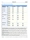
5 Of STEAM per hour per 100 ft.
6 Of STEAM MainSteamPressure(psig)2 2-1/2 3 4 5 6 8 10 1214 16 18 20 24 Temperature at 70 F Based on Sch. 40 Pipe Up to 250 PSI. Sch. 80 Above 250 PSI. Sch. 120 5 & Larger Above 800 PSI0 FCorrectionFactor Running LOADS in Pounds of
7 STEAM per hour per 100 ft.
8 Of STEAM MainSteamPressure(psig)2 2-1/2 3 4 5 6 8 10 1214 16 18 20 24 Temperature at 70 F Insulation 70% Efficient. 0 FCorrectionFactor Pipe Size428 Jones Boulevard Limerick Airport Business Center Pottstown PA 19464 Tel: 610-495-5131 Fax.
9 PSIG Saturated SteamFor other pressures use correction factors0 ,000234510,000234510,000678234510,0002 STEAM Flow lbs/hrPressure Drop psi/100 factor3/4"1"1-1/4"1-1/2"2-1/2"2"3"4"5"6" 8"10"12"14"16"18"20"24"350 DROP IN SCHEDULE 40 PIPE192 Watson McDaniel reserves theright to change the designsand/or materials of itsproducts without notice. 2006 Watson McDaniel Company* Shaded portion is for sizing temperature pilot, solenoid, or temperature-solenoid combination valves only.
10 + Specify Low Pressure T PilotEngineeringSIZING STEAM PIPESS aturated STEAM lines should be sized for a STEAM velocity of 4800 to 7200 on pressure reducing stations should be sized for the same STEAM velocity onboth sides of the regulator. This usually results in having a regulator smaller than thepiping and having larger piping on the downstream side of the using STEAM Velocity Chart (opposite page):100 PSIG Inlet Pressure to control valve25 PSIG Outlet Pressure1000 lbs/hr flow rateDetermine pipe size requiredUpstream Piping: Enter Velocity Chart at A1000 line to B100 PSIG Inlet PressureFollow line vertically upwards to C1-1/2 Pipe DiameterSteam Velocity at Dshows 4800 Piping.