Transcription of Carlon Rectangular
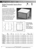
1 Carlon Rectangular Floor Box, ActivationKit and CoversInstallation InstructionsIS12525701 Science Park Drive, Cleveland,Ohio 44122 USACALL TOLL-FREE OR FAXTel: (800) 3- Carlon (1-800-322-7566) In Ohio: (216) 464- 3400 FAX: (216) 766-6444 TDD/Hearing Impaired Access: (216) Gang Application 1. Single gang box comes assembled. Two Gang Application 1. Two single gang boxes are required (2 pieces of E976 RFB). 2. Remove the appropriate side of each box to gang them properly. (Fig. 1) Slideboxes together by aligning the top interlocking tabs on the side of the baseand the bottom tabs and slots. (Fig. 2 and Fig. 3) THESE BOXES DO NOTSNAP TOGETHER; THEY SLIDE TOGETHER! Three Gang Application 1. Three single gang boxes are required (3 pieces of E976 RFB). 2. Repeat step 2 under Two Gang Application instructions. NOTE: When ganging 2 or 3 boxes, you must apply a piece of duct tape alongeach side and bottom seam.
2 (Fig. 4 and Fig. 5) 1. Set box on level surface with minimum concrete pour of 31/2". NOTE: With 3 1/2"concrete pour, space for cord plug between electrical device and closed cover is 7/8". 2. Set the box so there is a minimum 1/2"exposure after concrete pour. IMPORTANT! For abovegradeinstallation, provide adequate concrete thicknessunder the floor to preserve the fire rating of the floor in accordance with thebuilding codes. 3. Secure plastic cap to floor box before pour by cross taping the cap.( ) a. For two gang applications, cut the edge of one cap, then overlap the tape the underside For three gang applications, cut both edges of center cap. Overlap bothouter caps onto center cap and duct tape both underside Connections1. Use Carlon PVC cement to adhere Carlon Plus 40 or Carlon Plus 80 nonmetallic conduit or Flex Plus Blue ENT (electrical nonmetallic tubing) to utilized To feed parallel runs of 3/4"conduit use Carlon Y adapter Use Carlon PVC cement to adhere reducer-plugs (provided with Floor Box) toseal off unused conduit Floor box sides may be drilled for conduit feeds; to access, stay above noticeable scribe lines on side.
3 ( )IMPORTANT! Follow solvent cement manufacturers instruction and safety Concrete Pour Carlon Rectangular Floor Box E976 RFBP lastic capSideTo remove side, push up on side from 7 Fig. 6 Cut along both edges (3 gang)Scribe lineCut along edge (2 gang)In Canada, contact: Box 60 35 Killaloe RoadUnit 4 Concord, OntarioCanada L4K 1A0(905) 660-7993(888) 269-9902 Fax: (905) 660-9663(888) 229-86221 Top - Fig. 2 Bottom - Fig. 32 gang assembly3 gang assemblyDucttape#8 x 3/4 screwsDucttapeDividerActivation Yokes#8 x 3/4 screwsActivation YokeFig. 1 Fig. 4 Fig. 5 Gross Automation (877) 268-3700 Out After Concrete PourSingle Gang Yoke InstallationTwo and Three Gang Divider and Yoke Installation1. Remove plastic Determine floor box height and mark cut off line. (Fig. 8)a. For Carlon Nonmetallic Cover Installation go to page 3., steps 1, 2 and For Carlon Brass Cover Installation go to page 4, steps 1, 2 and Using handsaw, cut off box at marked height.
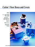
4 (Fig. 9)NOTE: Carlon Device Mounting Yoke may be either recessed down in the floor box,or installed directly to bottom of the Carlon Activation Kit E976AK2 InstallationDividerActivation Kit: Yoke/Activation ring Divider Insert plates ScrewsYokeDividerFig. 13 PlatesGround lug Fig. 11 LowvoltageplateFig. 12 Fig. 102 Box cutoff heightFig. 8 Fig. 9 Yoke Recessed in Floor Box1. Align Yoke in Floor Box slots (Fig. 7) and move yoke to desired Insert #8 x 3/4" pan head screws provided in Activation Kit into angled holes atthe ends of Yoke and tighten into Floor Box Mounted directly to Carlon Nonmetallic Covers1. Position Yoke on underside of Fasten Yoke to Cover using four #6 x1/2" flat head screws provided inActivation Mounted directly to Carlon Brass Covers1. Position Yoke on underside of Cover and retain in place using two #8 x 11/8"pan head screws provided with Insert #8 x 11/8" pan head screws into angled holes at the ends of cover andtighten into Floor Box !
5 It is necessary in accordance with NEC regulations to keep low voltage (voice, data or video) separate from power requirements. To comply, Divider provided in Activation Kit must be If using two or three gang box for either all power or all communication, Divider( ) is not required. Go to Step 5 per your Break off the edge of the Yoke (score line) on the side that the Divider is to belocated. ( )3. Cut Divider to For Carlon Nonmetallic Cover, cut Divider 3/4" below carpet flange underside atinstalled For Carlon Brass Cover, cut Divider 1/4" below carpet flange underside atinstalled Slide divider down into slots created when 2 or 3 Carlon E976 RFB Floor Boxesare ganged together. (Fig. 10)Yoke Recessed in Floor Box5. Align Yoke in Floor Box slots (Fig. 5) and move yoke to desired Insert #8 x 3/4" pan head screws provided in Activation Kit into angled holes atthe ends of Yoke and tighten into Floor Box Automation (877) 268-3700 Mounted to Carlon Nonmetallic Covers5.
6 Position Yoke on underside of Fasten Yoke to Cover using four #6 x 1/2" flat head screws provided in Activation Mounted to Carlon Brass Covers5. Position Yoke on underside of Cover and retain in place using two #8x1-1/ 8" pan head screws provided with Insert #8 x 11/8" pan head screws into angled holes at the ends of cover and tighten into Floor Box Attach conductors to a standard electrical device (Duplex, GFCI or Single Round receptacle).Canadian Applications:Per Canadian electric code, a separate bonding connection is required in nonmetallicelectrical boxes. Utilize Grounding Lug (Fig. 11) and green Ground Screw provided with Install electrical device in Yoke with device furnished 6-32 Attach the appropriate device plate using #6-32 x 5/8" oval head screw(s) provided in Activation Nonmetallic Covers InstallationE9761__*, E9762__* & E9763__**B=Brown; C=Caramel; S=SlatePlate Installation Power ApplicationsPlate Installation Low Voltage (Voice, Data & Video) Applications31.
7 A 6 port Low Voltage Plate (Fig. 12) is included in Activation Kit E976AK2. The Low Voltage Plate will acceptthe following Manufacturer s Keystone style jacks:- Allen Tel - Amp - Dynacom - Homaco - Hubbell - Krone - Leviton - 3M - Ortronics - Wiremold -Hellermann Tyton 2. Following Manufacturer s instructions connect wire or cable to the jack(s). Snap wired jack(s) into Low VoltagePlate with jack(s) aligned in the UP position. Snap blank modules into unused Attach the Low Voltage Plate to the yoke using #6-32 x 3/4" oval head screws provided with Low Voltage Plate. Fig. 14 FloorCovering#8 X 11/8''Cover mtg. screwsCord doorCord doorFig. 15 CarpetFlangeCoverScore lineNOTE: Carlon Activation Kit E976AK2 is required for carpet flanges will conceal opening sizes as follows: Single Gang 73/8" x 51/8", Two Gang 73/8" x 81/2" and Three Gang 73/8" x 113/4".
8 1. Determine type and thickness of floor covering to be used. Covers may be installed in carpet, tile or other floor : Remember to check height of finished floor Mark a line a 1/8" below desired final installed height of nonmetallic Cover s top surface. Using a saw, cut off box at marked height. (Refer to page 2, Trim Out After Concrete Pour)3. Methods of Installationa. Tile or Carpet:The cover may either be installed as is with carpet flange or,b. Tile:Carpet flange may be removed using a sawsall, jig saw or saber saw to cut alongthe score lines. Avoid using pliers or similar tools to break away the flange. (Fig. 14)If option of removing carpet flange is selected, set Cover so top surface of flangeis at finished tile height. Work tile to Cover Carpet:Install carpet up to Floor Box outside Tile or Carpet:Cover may be inverted and a section of carpet or tile installed inthe Cover to make the Cover less noticeable.
9 Use template on page 4, Fig. 17, tosize section of floor covering to be installed in inverted cover. If inverted coveroption is chosen, small Cord Door must be removed and re-installed on theopposite side of the cover. (Fig. 14)4. Yoke provided in Activation Kit may be either mounted directly to bottom of theNonmetallic Cover or recessed down in the box. See Activation Kit Installation page To attach Cover to Floor Box, insert #8 x 11/8"pan head screws (provided with Cover)into angled holes at the ends of Cover and tighten into Floor Box ends. (Fig. 15)Gross Automation (877) 268-3700 Rev. 2/00 Lamson & Sessions 199925701 Science Park Drive,Cleveland, Ohio 44122 USACall toll-free or faxTel: (800) 3- Carlon (1-800-322-7566) In Ohio, (216) 464-3400 FAX: (216) 766-6444 TDD/Hearing Impaired Access:(216) 831-5918In Canada, Box 60 35 Killaloe Road, Unit 4 Concord, Ontario Canada L4K 1A0(905) 660-7993 (888) 269-9902 Fax: (905) 660-9663 (888) Brass CoversE9761BR, E9762BR & E9763 BRNOTE: Carlon Activation Kit E976AK2 is required for flanges will conceal opening sizes as follows: Single Gang63/4" x 41/2", Two Gang 63/4" x 73/4" and Three Gang 63/4" x 11".
10 1. Determine type and thickness of floor covering to be used. Covers may be installed in carpet, tile or other floor : Remember check height of finished floor Mark a line a 3/16" below desired final installed height of BrassCover s top surface. Using a saw, cut off box at marked height.(Refer to page 2, Trim Out After Concrete Pour)Caution:If 11/2" or more is removed from top of box, larger section of support ribs on the ends of the box may be above concrete. If needed, remove top of end support ribs to allow finished floor covering to be installed within 5/8" of box Methods of Installationa. Tile:Set Cover so top surface of flange is at finished tileheight. Work tile to Cover Carpet:Install carpet up to Floor Box outside Yoke provided in Activation Kit may be either mounted directly tobottom of the brass cover or recessed down in the box. SeeActivation Kit Installation page To attach Cover to Floor Box: Insert #8 x 11/8" pan head screws(provided with Cover) into angled holes at the ends of Cover andtighten into Floor Box ends.