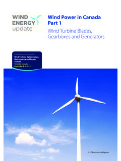
Transcription of Case Study Analysis Planetary Gearbox Sept 5 2006
1 1 of 12 case Study Two Stage Planetary Gearbox - Ken Singleton Sept 4, 2006 case Study Analysis of Two Stage Planetary Gearbox Vibration KSC Consulting LLC Ken Singleton Manager Abstract: A two stage Planetary Gearbox used in underground coal mining experienced an overload in service which caused bearing and bolting failures. The Gearbox was repaired and underwent a no load spin test. A very audible noise was present in the vicinity of the 1st stage gear set. Vibration Analysis was used to determine the source of the vibration. The equations for calculating the Planetary gear shaft speeds, gear meshing frequencies, and bearing frequencies in the Gearbox are provided. Background: Gearboxes used in underground coal mining are of compact design. A typical two stage Planetary Gearbox , 800 HP, :1 Ratio with 1800 RPM input is shown in Figure 1. The unit was received by a repair facility for rebuild following failure from an overload incident.
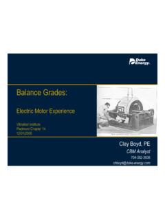
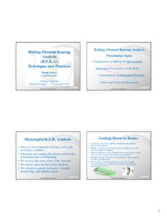
2 It was reported that the bearings were replaced and that one bearing had broken into many fragments. Following repairs a no load spin test of the Gearbox was performed as a check for bearing faults, Figure 2. There was an audible impacting type noise from the input Planetary section. Analysis : During the spin test, vibration data were measured using an accelerometer with rare earth magnetic mount. Initial inspection of the data indicated impacting and ringing of natural frequencies of the Gearbox , Figure 3. The impacts measured a mSec period or Hz ~ CPM. The FFT of the time domain data showed harmonics of CPM and indication of excitation of several natural frequencies of the Gearbox . Figure 2. Gearbox On Test Stand For No Load Spin Test. Figure 2. Cutaway View of 2-Stage Planetary Gearbox , :1 Reduction. 2 of 12 case Study Two Stage Planetary Gearbox - Ken Singleton Sept 4, 2006 Before a determination of the source of the vibration could be made, an understanding of the Gearbox design was required and calculation of the excitation frequencies.
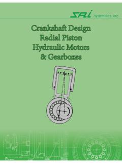
3 Based on the information provided by the drawing shown in Figure 1, several calculations were made to obtain the shaft speeds, bearing fault frequencies and gear meshing frequencies. Epicyclic gear boxes derive their name from the epicyclodial curves that the planet gears produce during rotation. There are three general types of epicyclic arrangements, 1) Planetary which consists of a stationary ring gear combined with a rotating sun gear and moving planet carrier, 2) star configuration which consists of a stationary planet carrier coupled with a rotating sun gear, and 3) solar gear that has a fixed sun gear combined with a moving ring gear and planet carrier. The Planetary arrangement is most common and is shown by the schematic in Figure 4. The subject Gearbox had the Planetary arrangement for the 1st and 2nd stages. Input was from the sun with three planets supported by a carrier revolving about the sun pinion and the ring gear fixed.
4 Figure 3. Vibration Signal Measured at Gearbox Input Section Showed Impacts at mSec Interval ~ Hz ~ CPM. The FFT (Top Plot) Indicated Excitation of Several Resonant Frequencies Including A Very Response One at About 66,000 CPM ~ 1,100 Hz. Route W av eform 16-Mar-06 08:48:16 RMS = .3743 PK(+/-) = CRESTF= 0123456789-3-2-10123 Revolution NumberAcceleration in G-sLW - Joy L700EP 40. 173SN-85836 -P2H Pt 2 Hor Input ShaftRoute Spectrum 16-Mar-06 08:48:16 OVERALL= .0802 V- AN RMS = .3892 LOAD = R PM = 506. ( H z) 0200004000060000800001000000 0. 030. 060. 090. 12 Frequency in CPMRMS Acceleration in G-sResonance at about 66,000 CPM mSec ~ Hz ~ CPM3 of 12 case Study Two Stage Planetary Gearbox - Ken Singleton Sept 4, 2006 1st Stage 2nd Stage SS Sun Gear RPM (Input Speed) 1782 RT Ring Gear Teeth 112 73 PT Planet Gear Teeth 47 27 ST Sun Gear Teeth 17 17 Tvalue Train Value Carrier RPM PS Planet RPM PSabsolute Planet RPM Absolute RS Ring Gear RPM 0 0 PGMF Planet Gear Meshing Freq CPM 26, , FGMF-Sun Sun Gear Meshing Freq CPM 30, , Ratio Stage Ratio step 1: Carrier Speed The 1st stage carrier speed can be calculated as follows.
5 Train value: The 1st stage Carrier Speed then calculates to: The negative sign - indicates the carrier is rotating in the opposite direction to the sun gear. The 2nd stage carrier speed which is also the output of the Gearbox calculated to: The Gearbox ratio calculated to: The calculated ratio agreed with the ratio provided by the Gearbox manufacture of Figure 4. Gear Arrangement Of 1st Stage Planetary Input Section. 17 112 TTValueTTSPTPR === ( ) SSvalueRTSCRPMT == == ( ) SSvalueRTSCRPMT ==== 17 73 TTValueTTSPTPR === 1: Summary of The Gearbox Shaft Speeds and Gear Meshing frequencies. 4 of 12 case Study Two Stage Planetary Gearbox - Ken Singleton Sept 4, 2006 The carrier speeds can also be calculated as follows: The 1st stage carrier speed: The 2nd stage carrier speed: 112 ++== = =73 ++== = =5 of 12 case Study Two Stage Planetary Gearbox - Ken Singleton Sept 4, 2006 step 2: Planet Speed The 1st stage planet rotational frequency or planet spin speed was calculated as follows: The 1st stage absolute planet rotational frequency can be determined by summing the carrier and planet rotational frequencies algebraically.
6 Note that this frequency seldom appears in vibration data. The 2nd stage planet spin speed calculated as follows: The 2nd stage absolute planet rotational frequency is then determined: The planet speed can also be calculated as follows: 1st stage planet RPM: 2nd stage planet RPM: = = AbsolutessPCPRPM=+= += = = += +=112()( ) = = 73()( ) = = 6 of 12 case Study Two Stage Planetary Gearbox - Ken Singleton Sept 4, 2006 step 3: Gear Meshing Frequencies The planet gear meshing frequencies were then determined for stage 1 as follows: The higher frequency sun gear meshing frequency was calculated: The 2nd stage planet gear meshing frequencies were then determined as follows: The 2nd stage sun gear meshing frequency was then calculated: 4726, = =1782 17 30, 294 GMFsTSSSCPM= = = 27 3, = = 17 3, = =7 of 12 case Study Two Stage Planetary Gearbox - Ken Singleton Sept 4, 2006 step 4: Bearing Fault Frequencies After the Gearbox shaft speeds were determined, the bearing fault frequencies were calculated and listed in Table 2.
7 For purposes of calculating the bearing fault frequencies of the planet bearings, the spin frequency of the planets must be summed to the carrier rotational frequency. Since the outer race was turning faster the calculations were made as if the bearing inner race was not rotating. Stage 1 Planet Spin Freq + = RPM Stage 2 Planet Spin Freq + = RPM Note that dimensions were not located in the time allowed for the cylindrical roller bearing NUP 3972 . 1X Brg Fault Frequencies CPM Component Brg Inner Race RPM (Relative to Outer Race) FTF BSF BPFO BPFI Sun NU228E Sun 6226 1st Stage Planet NJ314 Output Carrier NCF 1864B Output Carrier NUP 3972 2nd Stage Planet JN2318 The bearing fault frequencies were calculated using Machinery Health Manager software (CSI RBMware).
8 Equations from Reference 2 are provided below. Table 2: Listing of Gearbox Bearings and Fault Frequencies CPM. 1() = {1 ()c o s} ndBall SpindPD = {1 () c o s } RacendBall PassZPD = {1 () c o s } RacendBall PassZPD = + Where: 3740 deg (73, 74)toSeries =(),sec60 CyclesRPMn Shaft FreqeuncyorHz=..(..)2O D boreP DPitch Diameter For ball bearings P D+==dRolling Element Diameter=()ZNumber of balls or rollers per row=0degBearing contact angleree for pure radial load =1520 deg (sec)tothinnertion bearings = 10 15 degtospherical roller typical range =8 of 12 case Study Two Stage Planetary Gearbox - Ken Singleton Sept 4, 2006 step 5: Determination of Vibration Source Referring to the data plots in Figure 3, it was readily determined using the vibration software cursors that the impulse frequency was Hz ~ CPM.
9 A check of the frequencies in Table 2 showed that this frequency does not match any of the bearing fault frequencies. A check of the Gearbox shaft speeds and gear meshing frequencies in Table 1 also did not immediately identify a forcing frequency. The pulses in the time domain measured mSec ~ Hz ~ CPM. Since the Gearbox has three planets in each stage an impulse could occur at three times the 1st stage carrier frequency of CPM if there were damage to the ring gear teeth. This frequency was calculated as follows: The source of the pulses was related to rotation of the carrier and the three planets in the 1st stage also called the planet passing frequency. Updating Table 1 to include the planet passing frequency, Table 1A: 1st Stage 2nd Stage SS Sun Gear RPM (Input Speed) 1782 RT Ring Gear Teeth 112 73 PT Planet Gear Teeth 47 27 ST Sun Gear Teeth 17 17 Tvalue Train Value Carrier RPM PS Planet RPM PSabsolute Planet RPM Absolute RS Ring Gear RPM 0 0 PGMF Planet Gear Meshing Freq CPM 26, , FGMF-Sun Sun Gear Meshing Freq CPM 30, , PPass Planet Passing Freq Ratio Stage Ratio 3 ~ =Table 1A: Summary of The Gearbox Shaft Speeds, Gear Meshing and Planet Passing Frequencies.
10 ~ of 12 case Study Two Stage Planetary Gearbox - Ken Singleton Sept 4, 2006 Expanding the time domain plot to show only two pulses, Figure 5, the pulses ring down which is typical response of structural resonance. The spectrum data also provided clear indication of resonance excitation. Plotting a single pulse in Figure 6 showed more clearly the time between oscillations was about mSec or 57,600 CPM. Note that spectrum analyzers don t make good oscilloscopes due to the rather course sampling at times the maximum frequency to be displayed in the frequency spectrum. LW - Joy L700EP 40. 173SN - 85836 - P1H Pt 3 Hor 1st St age Plan etRoute W av eform 29-Mar-06 13:26:54 RMS = .7497 LOAD = R PM = 506. ( H z) PK(+) = PK(- ) = CRESTF= 140150160170180190200-4-3-2-101234 Time in mSecsAcceleration in G-sTime: Amp l : Dtim: Freq: 6.