Transcription of Cassegrain Telescopes for Amateurs
1 Cassegrain Telescopes for Amateurs By: Jeffrey D. Beish (Revised: 26 September 2014) INTRODUCTIONIn the late 1970 s several of the local amateur telescope Makers (ATM) in Miami,Florida got together and began making Telescopes . Up until then a 6-inch reflector or refractor was considered a fairly large telescope , but to own a was considered heavy duty observing. So, we began with mirrors and while some ground and polished their own mirrors some of us opted to have someone else do it. While the wide field observers would build shorter focal ratioNewtonian reflectors I chose a more complex design; the Classical Cassegrain Telescopes are less expensive than refractors and when properly designed they can equal the high contrast images of a refractor without the associated chromatic aberration. Of course, the "roll-your-own" idea usually reduces this cost even further.
2 But remember, this can vary greatly according to how large the aperture is. The larger the aperture -- the higher the cost. Don t forget you do have to account for the cost of the tools used in the with the highest quality optics a reflecting telescope can be rendered nearlyuseless by tube currents, misaligned components, mirror stain, and a secondary mirror too large for the application of the instrument. The size of the secondary mirror and how it affects image contrast will be the main topic discussed here. Some fundamentals in Cassegrain design will be discussed along with methods of optimizing existing Telescopes if one chooses not to build from the ground up. To determine the correct focal plane image diameter one consideration is the field lens in your collection of eyepieces. You may want to choose from the diameters of eyepieces you use and then go from there to determine the nominalimage diameter at the focal most of our group either made their own or had a f/4 mirror made, this would fit well with a Cassegrain design.
3 So I laid out the ray tracing and requirements for a Cassegrain telescope for planetary observing. There are not many amateur telescope makers (ATM) today who build Cassegrain Telescopes . However, there are interesting features of this design that makes it well worth investing the effort and money to build such an instrument. In my mind it was well worth the time and effort to build my first f/4 f/16 Classical Cassegrain and subsequently to upgrade it to a longer effective focal ratio telescope to increase the image contrast and also to get rid of some pesky mechanical Classical Cassegrain DesignFrom several different types of Cassegrain Telescopes I chose the Classical design with the parabaloid primary and convex hyperboloid secondary. Reading material on hand and Richard Berry s first ever issue of telescope Making Magazine in the Fall of 1978, the first article, " Cassegrain Optical Systems," by: Dr.
4 Richard A. Buchroeder, was all that was needed to get started. Also, a great read is Cassegrain Notes by Kenneth F. Novak that is now available on the Internet. The Classical system seemed to be the best choice due to less field curvature, availability for polishing tools and the fact that our local optician, Richard Fagin, had experience making them. From the available documents the following mathematical treatment was found and calculation began: Cassegrain Equations: p = (F + b) / (X + 1), p = pX , B = p b, c = Dp / F + Bi/ FX,Where: p = primary focus intercept point, p = secondary to Cassegrain focus, F = primary focal length, X = secondary magnification, b = back focus, B = mirror separation, c = secondary clear aperture, i = final image size, D = primary diameter [ Buchroeder, 1978].
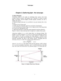
5 NOTE: The separation between primary and secondary mirrors in a Classical Cassegrain reflector is critical. However, a small difference can be tolerated and is computed from: (B) = 4 (if in centimeters then (B) = FR 4 ) , where FR is the focal ratio of the primary and the separation can be of 45% closer (-B) togetheror 55% further apart (+B) is tolerated[ Cox and Sinnott, 1976].The minimum diameter for the Cassegrain secondary mirror: cmin = Dp / F . If the secondary mirror is already made the final image can be determined by: i = X(cF Dp) / 1. The Cassegrain telescope optical equations. Cassegrain Equations for description of terms in drawing: primary focus intercept point (p), secondary to Cassegrain focus (p ), primary focal length (F), secondary magnification (X), back focus (b), mirror separation (B), secondary clear aperture (c), final image size (I), primary diameter (D).
6 Baffles and Glare StopsOne factor in the design is the size and position of baffles and glare stops to prevent direct and indirect light from entering the eyepiece from the tube entrance and walls. Glare stops are often found in eyepieces, so, the placement and size can be determined by using the same equations as discussed herein forCassegrain baffle baffle tube is usually placed in the primary mirror center hole in the typical Cassegrain design. In this case, the baffle tube is held in place by some solid insert in the primary mirror hole and actually touches the mirror glass. Stresses on the glass may happen and the attaching hardware can store unwanted heat. This author has found that attaching it to the mirror cell is best and it is possible to design the baffle tube to be adjustable. Adjusting the baffle tube attached to the mirror hole is difficult and may not stay in place for very determining the size of baffle tube it is easier to use materials available in localhardware stores.
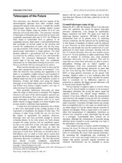
7 To the delight of many ATM there is an endless supply of tubes and gadgets found at a local hardware store or junkyard. Ordinary household plumbing fixtures, such as brass and PVC sink traps, come in handy and make perfect Cassegrain baffles. They come in several sizes from to 2-inches in diameter and lengths of 6 to 18 inches. Also, sink traps can be fitted together to form even longer baffles if needed. I have used PVC and brass sink traps in the past with great results; however, PVC is lighter and easier to work with. Cassegrain Baffle Tube Equations: The general equation for calculating the length of the baffle tube is: L1 = (WB + Wb - cb - iB) / (c - i)Where, W = baffle , B = mirror separation, b = back focus, K = secondary holder outside diameter, i = final image size, c = clear secondary aperture and V = baffle tube outside diameter.
8 [ Novak , 1978]. NOTE: Cassegrain Notes ( Novak , 1978 ) has a typo in the first baffle formula; where equation (4) has cB and should be cb in the third variable as shown in the above equation (L1).If the walls of the tube are too thick then the baffle may be too long and block off light reflected from the primary to the secondary; therefore reducing illumination and contrast. Two additional equations are used to find the minimum baffle tube length (L2), so if the tube is too short then stray light will enter into the focal plane. The maximum baffle tube length (L3) that will not block off light reflected from the primary to the secondary. Here are two equations to test these conditions: Minimum baffle tube length: L2 = (WB + Wb - Kb - iB) / (K - i) Maximum baffle tube length: L3 = F(K - V) / KIf L3 is shorter than L1 or L2 it stands to reason that the first two calculations produce a baffle tube that is too long.
9 The way to shorten it is to either use a smaller inside diameter tube or one with thinner walls, or both. You can work with the above equations and test several tube diameters and wall thicknesses tomake L1 and/or L2 less than may be desirable to use a secondary mirror holder baffle; however, this may result in a slight increase in the secondary obstruction. To calculate the secondary holder baffle length (L4) from the mirror face:secondary holder baffle length: L4 = B(K - c) /DWhere, B = mirror separation, K = secondary holder outside diameter, c = clear secondaryaperture and D = primary diameter. Ray tracing various tube diameters and lengths the positions for each glare stop was determined so to prevent light reflecting from baffle wall down the tube to thefocal plane. Then the diameter for each stop has to be determined.
10 In the glare stop equation listed below the sign to the Z term can be manipulated to calculatethe diameter of each glare stop within the baffle tube. Term Z is the distance from behind the primary face to the position of the stop and usually presented in literature to calculate the rear glare stop. Changing the sign to minus (-) would put the stop in front of the primary face or somewhere along the baffle tube towards the , the smooth material inside the baffle tube may cause light scatter in the optical path, so it can be lightly threaded in a lathe to rough up the material and after a light coat of flat black paint light scatter was significantly reduced. Flocking paper may also be applied to the insides of the tube, but remember that this will reduce the baffle tube ID. Typical flocking paper thickness is , so reduce the baffle tube by and recalculate the length.