Transcription of CAVITY WALLS - MAC
1 CAVITY WALLSD esign Guide for Taller CAVITY WALLS THE BOTTOM LINEA side from the finished product being of considerable beauty and formidable strength,other initial and long-term benefits are gained when CAVITY wall systems are coupledwith the structural entities previously cited. INITIAL BENEFITS The statement that " masonry is too expensive" is just a myth. CAVITY wall systems are initially lower in cost than many glass curtain WALLS , metal panel curtain WALLS ,granite panels, marble panels, and architectural precast concrete WALLS . Add to thisa reduction of $ per lineal foot of shelf angle deleted, and additional savingsoccur. Limiting the number of crafts involved promotes rapid construction resulting in sav-ings due to early occupancy. All materials required are usually available locally, which eliminates costly shippingcharges and untimely TERM BENEFITS CAVITY WALLS are energy efficient when considering the life cycle cost of a building.
2 Atypical "R" value can be increased if greater energy-efficiency is desired. A structure built with the type of systems previously discussed provides a built-in, 2-to-4 hour, fire -rated barrier. Annual fire insurance premiums can be reduced bynearly 1/3, depending upon the type of construction chosen, and its occupancy. masonry construction is very economical with respect to long-term Technical Note 16, Rev fire resistance , BrickIndustry Association, Reissued Oct. Technical Note 18 series, Differential Movement,Cause and Effect, Expansion Joints, Flexible Anchorage ,Brick Industry Association, Jan. 1991, December Technical Note 21 series, Brick masonry CAVITY WALLS ,Insulated, Detailing, Construction , Brick IndustryAssociation, Aug. 1998, Feb. 1999, Feb. NCMA TEK 3-12 Loadbearing Concrete Block in HighRise Buildings National Concrete masonry Association, NCMA TEK 5-2A, 10-1A, & 10-2B Control of WallMovement with Concrete masonry National ConcreteMasonry NCMA TEK 14-10 Lateral Support of ConcreteMasonry WALLS National Concrete masonry Association, NCMA TEK 5-6A.
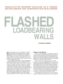
3 Details 2001: NCMA TEK 5-7A Floor and Roof Connections to WALLS Manual for the Design of Hollow Core Slabs ,Prestressed Concrete Institute, Introduction of CAVITY WALLS - Letters CharteredSurveyor Weekly, (published in ), March28, 1985, pp. 707, 708 March 14, Reinforcing Steel in masonry , masonry Institute ofAmerica, January 1 INTRODUCTIONS imply stated, a CAVITY wall is two wythes of masonry ,separated by a CAVITY of varying dimension. The mason-ry wythes may consist of solid brick, structural clay tile,or concrete masonry units and are bonded together withmasonry ties. The CAVITY (ranging from 2 inches to 4 1/2inches in width) may or may not contain insulation. SeeFigure 1. Combining these elements with a sound struc-tural design, appropriate details, quality materials andgood workmanship will result in high performance cavi-ty WALLS are not new, they have been observed inancient Greek and Roman structures.
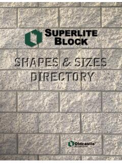
4 At the GrecoRoman town of Pergamum, on the hills overlooking theTurkish town of Bergama, a stone wall of CAVITY typeconstruction still in the early part of the 19th century, the cav-ity wall was probably reinvented by the British. Plansdating as early as 1805 suggest a type of construction,featuring two leaves of brickwork, bonded by headersspanning across a 6-inch CAVITY . An early British publi-cation (dated 1821 ) suggests the use of CAVITY WALLS asa means of protection against moisture penetration. Theuse of metal ties was introduced in Southern Englandsometime after 1850. These original ties were made ofwrought WALLS were first built in the United States late inthe 19th century. Figure 2 illustrates an alternate type ofcavity wall system originally featured in an 1899 textbook assembled for people engaged in the engineeringprofessions and construction trades. However, it wasnot until 1937 that this type of construction gained offi-cial acceptance by any building or construction agencyin the United States.
5 Since then, interest in and use ofcavity WALLS in this country has increased rapidly. Thishas resulted in extensive testing to determine cavitywall properties and early use of CAVITY WALLS in this country was limitedprimarily to exterior load-bearing WALLS in low rise con-struction. In the 1940s, designers began to recognizethe advantages of CAVITY WALLS in high-rise , masonry CAVITY WALLS are used extensivelythroughout the United States in all types of primary reasons for their popularity are superiorresistance to rain penetration, excellent thermal proper-ties, excellent resistance to sound transmission andhigh resistance to fire . 2 PROPERTIES OF CAVITY WALLSRESISTANCE TO MOISTURE PENETRATIONNo single unreinforced 4" wythe of masonry is totallyimpervious to moisture penetration. A CAVITY wall isdesigned and built as a moisture-deterrent system takes into account the possible moisturepenetration through the outer wythe.
6 Moisture willpenetrate masonry WALLS where hairline cracks existbetween masonry unit and mortar. Water which runsdown the exterior wall surface will be drawn towardsthe inner CAVITY due to wind pressure exerted on theexterior of the wall and the negative pressure presentwithin the CAVITY . Providing a clean air space willallow this moisture to flow unobstructed down thecavity face of the outer wythe. Flashing installed atrecommended locations will then divert this moistureback to the building's exterior through drainage of moisture will reduce the chanceof efflorescence and freeze-thaw ENERGY EFFICIENCYAt one point in time, energy conservation was not amajor consideration in building design. CAVITY wallswere primarily built for their structural and moisturediverting qualities. During the mid 1970's, designersbecame aware of the life cycle cost of buildings sothe design of energy efficient WALLS were CAVITY became an excellent place to insert insu-lation, minimizing heat loss and heat gain.
7 Bothwythes act as a heat reservoir, positively affectingheating and cooling modes. The isolation of the exte-rior and interior wythes by the air space allows alarge amount of heat to be absorbed and dissipatedin the outer wythe and CAVITY before reaching theinner wythe and building ability is further increased by the use of closedcell rigid insulation in the CAVITY . A foil faced, polyiso-cyanurate insulation is the most beneficial for threereasons: it yields an R value of per inch of thick-ness, its R value is not affected by the presence ofmoisture, and its foil back enclosure creates a reflec-tive air space that increase the WALLS overall R valueby approximately The R value of a typical cavitywall may range from 14 to 26 depending on the typeand thickness of insulation RESISTANCER esults of the ASTM E-119 fire resistance Testsand the contents of both the fire Protection PlanningReport (CMIFC)2and the fire resistance (AISG)3clearly indicate that masonry cavitywalls have excellent fire resistance .
8 All CAVITY wallshave a fire rating of 4 hours or PROPERTIESM asonry's capacity as a load bearing material issuperb, yet its structural potential is often principle factors affecting the overall compres-sive strength of a wall are: the compressive strengthof the individual units, the type of mortar, and thequality of workmanship. Tables 2 and 3 lists theassumed compressive strength (f'm) for brick andconcrete masonry . For large projects prism testing ispreferred since actual values are usually higher thanthe assumed strengths. The tables indicate that a standard concrete mason-ry unit with a type N mortar (1:1:6 by proportion) willyield a minimum f'm of 1500 psi. This strength is suf-ficient for most mid to low-rise bearing wall addition to its excellence capacity as a bearing ele-ment, concrete masonry 's performance as a back-upsystem is superb. Each wythe in a CAVITY wall helpsresist wind loads by acting as a separate wall.
9 Thecross wire of the horizontal joint reinforcement trans-fer direct tensile and compressive forces from onemasonry wythe to the other. Tests have indicated thatjoint reinforcement also provides some transfer ofshear, approximately 20 to 30 percent, across thewall CAVITY . For a reference on allowable heights ofcavity wall see Table 4. 3 Exterior air film.. 4" Brick .. R of the reflective air space .. R of 2 Dow, Tuff R-C, polyisocyanurate insulation.. 6" CMU .. 1 1/2 air space ..R of 1/2 drywall .. Inside air film .. R of the total wall .. 1R VALUE BRICK AND BLOCK CAVITY WALL4 Clay Block (115#.ft3) = 72% Block (115#.ft3) = 59% Block (115#.ft3) = 54% Block (115#.ft3) = 52% Block (115#.ft3) = 48% air film (winter) air air space (3/4 to 4 ) (winter) * Reflective air type thickness (inches) Polyisocyanurate (foil face) Dow Tuff RTM/ ThermaxTMExtruded Polystyrene Dow, Owens Corning1/2 1 1 1/2 2 2 1/2 3 * Use this value when insulation has a foil backing directly adjacent to air space 4(unreinforced) 5 CAVITY TYPE BEARING WALLSGENERALWhen engineered, a CAVITY wallsystem can be designed to pro-vide both structure and theenclosing skin.
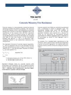
10 Building this sys-tem consists of constructing aseries of single story structures,one on top of the other. Thestructure can be erected at a rateof one floor per week by imple-menting a tight schedule and suf-ficient man power. Combiningload bearing CAVITY WALLS andprecast concrete plank floors canmake for efficient, economicaland speedy system relies upon compos-ite reaction between the mason-ry WALLS , the precast concreteplank floor, and the roof masonry and precastconcrete plank connectionstransfer wind induced shearstresses through the floordiaphragm to interior masonryshear WALLS (which may also beutilized as bearing WALLS ). Thistype of construction is ideal forlow and mid-rise constructionlike the Green Castle apartmentsshown 3 Green Castle (Elmhurst, IL) is constructed of CAVITY type bearing WALLS andspans 7 stories highLOAD CAPACITY INVESTIGATIONThe following calculations examine the load-bearing capacity of a sixstory CAVITY type bearing wall system.