Transcription of Ceiling Concealed Chilled Water Fan Coil Unit - Daikin
1 Ceiling Concealed Chilled Water Fan Coil UnitEngineer DataED-FWW-VC-201607 Models: FWW200VC FWW300VC FWW400VC FWW500VC FWW600VC FWW700VC FWW800VC FWW1000VC FWW1200VC FWW1400 VCAir Flow: 340-2380m3/h1 NOTE: Installation and maintenance are to be performed only by qualified personnel who are familiar with local codes and regulations, and experienced with this type of : Sharp edges and coil surfaces are a potential injury hazard. Avoid contact with : Moving machinery and electrical power hazard. May cause severe personal injury or death. Disconnect and lock off power before servicing equipment. Literature No.: ED-FWW-V-201501 Supersedes: ED-FWW-VC-201607 ContentsNomenclature.
2 2 Valve Nomenclature ..3 Features ..4 Specifications ..5 Sound Data ..6 Air Flow vs ESP Curve ..7 Operating Limits ..8 Water Flow Rate/Pressure Drop Chart ..9 Outlines and Data ..11 Wiring Diagrams ..12 Installation ..132 NomenclatureFWW 200 V C 3 R C X - A 0 A ESales Region: E: ExportPower Supply: A: 220V~/50 HzOther Feature CodesMaterial of Drain PanFilter: X: no filter F: 8mm nylon filter A: 8 mm aluminum filterReturn Air Plenum: C: without return air plenum E: back return air plenum(5mm PE insulation) F: bottom return air plenum(5mm PE insulation)Pipe Connection: R: facing air flow right hand L: facing air flow left handExternal Static Pressure: 1: 12 Pa 3: 30 Pa 5: 50 PaCoil Type: C: 3 rowsUnit Design SNRated Air Volume (CFM, 1 CFM = m3/h) Daikin Ceiling Concealed Horizontal Fan Coil UnitB: back return air plenumD.
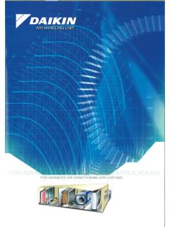
3 Bottom return air plenum3 Valve NomenclatureFWW - 2V 4 Y B R A EFWW- Daikin FCU (Only 2-pipe system is applicable)Valve model2V:2-Way Valve Kit3V:3-Way Valve KitUnion SizeOmitted-R3/44-R1 Pipe ConnectionR-for Right hand unitL-for Left hand unitE-ExportU-Stick "Made In China"Power Supply:A-220-240V/1Ph/50 HzK-208-230V/1Ph/60 HzValve TypeB-with Ball ValveX-without Ball ValveStrainer TypeY- with Y-StrainerX-without Y-Strainer4 FeaturesCompact Light-weighted, good-looking appearance, and compact and solid structure. 235 mm height, allowing installation on the Ceiling with a limited Low-noise motor for driving the low speed fan with a wide impeller; strictly tested before delivery.
4 Precise distance between the impeller inlet/outlet and the heat exchanger for more reasonable air flow distribution. Highly efficient sound-absorbing and heat-preserving materials inside to minimize noises produced by the unit. Reliable Single-phase capacitor motor with the protection grade IP20 and insulation grade B to ensure operation safety. Permanently lubricated and sealed ball bearing with high precision, which is provided by internationally famous brands and receives processing including hardening and tempering as well as chroming. Motor power outlet wires protected by metal hoses to ensure its durability.
5 Working pressure up to MPa and test pressure up to MPa for the heat exchanger to endure high pressures and prevent leakage. High Efficiency Heat exchanger with the high-quality mechanically expanded copper pipe and hydrophilic aluminum fins to ensure high efficiency. Intensified air supply using a large air flow fan with a wide impeller to maximize the heat transfer performance. Precise matching of the fan and motor to guarantee the maximum cooling capacity but a low power input. Flexible Multiple external static pressures designed based on the unit s cooling capacity, meeting the air supply requirements at different distances.
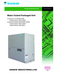
6 Optional bottom return air plenum or back return air plenum with support for onsite changes, featuring time saving. Variable accessories for more Delicate condensate-proof drain pan made of the cold-rolled steel through one-time impact molding, with coating on both sides and high-quality heat-preserving materials on the exterior. Unique independent mounting bracket without soldering seams or joints, requiring no bolts for fixing to prevent damages to the drain pan heat-preserving layer or cold bridges. Tilt structure for rapid condensate Water drainage. 5 SpecificationsGeneral DataNOTES:1) ALL SPECIFICATIONS ARE SUBJECTED TO CHANGE BY THE MANUFACTURER WITHOUT PRIOR ) ALL THE UNITS ARE BEING TESTED UNDER FOLLOWING CONTITION: COOLING-27 C C WB INDOOR AND Water INLET 7 C OUTLET 12 C HEATING-21 C DB INDOOR AND Water 60 C FLOW.
7 SAME WITH COOLING ) SOUND PRESSURE LEVEL ARE ACCORDING TO MICROPHONE POSITION OF THE MEASUREMENT POINT IS 1m IN FRONT ENDFWW-VCMODELFWW200 VCFWW300 VCFWW400 VCFWW500 VCFWW600 VCFWW700 VCFWW800 VCFWW1000 VCFWW1200 VCFWW1400 VCAir FlowHIGHm3/h3405106808501020117013601700 20402380 CFM200 300 400 500 600 688 800 1000 1200 1400 MEDIUMm3/h279418558697836959111513941673 1952 CFM164 246 328 410 492 564656 820 984 1148 LOWm3/h17025534042551058568085010201190 CFM100 150 200 250 300 344 400 500 600 700 EXTERNAL STATIC 12,30,50 , , COOLING CAPACITYW2220 3300 4260 5050 5820 6600 8200 9300 11190 13000 Btu/h7575 11260 14536 17231 19859 22520 27980 31733 38182 44358 SENSIBLE COOLING CAPACITYW1380 2220 2770 3400 4000 4550 5500 6500 7700 9200 Btu/h4709 7575 9452 11601 13649 15525 18767 22179 26273 31392 TOTAL HEATING CAPACITYW3500 5330 6800 8400 9600 11100 13500 15800 18300 21500 Btu/h11942 18187 23203 28662 32757 37875 46064 53912 62442 73361 Water FLOW RATEm3 HEAD LOSS (Cooling) UNIT WEIGHT(Without plenum) GROSS WEIGHT(Without plenum)
8 DIMENSIONSW ithout Return Air Plenummm625 465 235815 465 235865 465 235945 465 2351045 465 2351095 465 2351425 465 2351475 465 2351675 465 2351825 465 235 With Back Return Air Plenummm625 516 235815 516 235865 516 235945 516 2351045 516 2351095 516 2351425 516 2351475 516 2351675 516 2351825 516 235 With Bottom Return Air Plenummm625 497 235815 497 235865 497 235945 497 2351045 497 2351095 497 2351425 497 2351475 497 2351675 497 2351825 497 235 UNIT WEIGHT(With plenum) UNIT GROSS WEIGHT(With plenum) CONDENSATE DRAIN SIZER3/46 NOTES:ALL SPECIFICATIONS ARE SUBJECTED TO CHANGE BY THE MANUFACTURER WITHOUT PRIOR Data FWW-VCFWW200 VCFWW300 VCFWW400 VCFWW500 VCFWW600 VCFWW700 VCFWW800 VCFWW1000 VCFWW1200 VCFWW1400 VCFANTYPEGALVANIZED STEEL DOUBLE STAGE IMPELLER CENTRIFUGAL (BLADE: FORWARD)QUANTITY1222223344 MATERIALGALVANIZED STEELDRIVEDIRECT DRIVEDIAMETERmm150 PHAZE BALL BEARING CAPACITOR RUNNINGQUANTITY1111112222IP/INSULATION GRADEIP20 MATERIALHYDROPHILIC PER INCH17 AIR FILTER (Option)TYPENYLON/ALUMINIUM FRAMESIZELENGTHmm438 628 678 758 858 908 1238 THICKNESSmm8 NOTES.
9 1) ALL SPECIFICATIONS ARE SUBJECTED TO CHANGE BY THE MANUFACTURER WITHOUT PRIOR ) SOUND PRESSURE LEVEL ARE ACCORDING TO MICROPHONE POSITION OF THE MEASUREMENT POINT IS 1m IN FRONT AND 1m BELOW THE DataFWW-VCModelFWW200 VCFWW300 VCFWW400 VCFWW500 VCFWW600 VCFWW700 VCFWW800 VCFWW1000 VCFWW1200 VCFWW1400 VCSound Pressure Level (ESP: 12Pa) 39 Sound Pressure Level (ESP: 30 Pa) Sound Pressure Level (ESP: 50 Pa) 7 ESP, 12 PaESP, PaAir Flow vs ESP CurveESP, 30 PaESP, 50 PaAir Flow, m3/hAir Flow, m3/hAir Flow, m3/hESP, PaESP, PaFWW1200 FWW1000 FWW800 FWW700 FWW600 FWW500 FWW400 FWW200 FWW300 FWW1200 FWW1000 FWW800 FWW700 FWW600 FWW500 FWW400 FWW200 FWW300 FWW1200 FWW1000 FWW800 FWW700 FWW600 FWW500 FWW400 FWW200 FWW3008 Operating LimitsOperating LimitsFWW-VWater Circuit Max.
10 Water side pressure Min. Entering Water temperature 3 C (cooling) Power supply Operating voltage limits 10% Volt Operating frequency limits 2Hz PRESSURE DROP kPaWATER FLOW m3/hWATER PRESSURE DROP CURVE(3 Rows) Water Flow Rate/Pressure Drop ChartFWW-VCFWW700 VCFWW500 VCFWW300 VCFWW400 VCFWW200 VCFWW1000 VCFWW800 VCFWW1200 VCFWW600VC10301432263518744 DABC235151144651052026213124240 MCW400 VMCW600 VMCW500 VMCW1000 VMCW1200 VMCW800 VMCW300V1675147594514251045625865815AC43 7677857757123712871487627120212521452822 722402642592BD17751575152511451045965915 725 MCW700V109511958729074406306807608609101 24012901490F4206106607408408901220127014 70222342312301432263518744 ABC235151262131242516232180E146F40G30143 2263518744 ABC38235151105262131242497232E14616217(1 75)