Transcription of CEM7 DIESEL GENERATOR CONTROL PANWL PRO MANUAL
1 CEM7 proAuto-start digital controller ManualProfessional MANUAL | Electronics CEM7 Index Warning on the intellectual property 2008 HIMOINSA All rights is the owner and reserve all rights of ownership on any text or graphic image exposed inthis MANUAL . The permission to reproduce all or a part of this MANUAL must be obtained by HIMOINSA written use of the information given in this MANUAL , its resale and/or the damage to the Intellectual Property or Industrial rights will entail the responsabilities legally and HIMOINSA logo are HIMOINSA trademarks in Spain and other and limitation of legal responsabilityInformation given in the MANUAL , including texts, date and/or pictures, are supplied in their current status by HIMOINSA in order to facilitate the access to products to its dealers and clients.
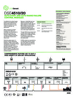
2 HIMOINSA is not responsible for the errors and/or omissions that may occur in this MANUAL and kindly recommends the commissioning and use of the products to be carried out only by qualified CEM and pHG exchanges comply with the following European standards:- Electromagnetic compatibility complies with the IN 61326-1:2006 standard - Electrical safety complies with the IN 61010-1:2001 standard3 | Electronics CEM7 Index 1. INTRODUCTION Visualization module Measurements module The measurements module provides the following readings of the electric mains supply (CEM7+CEC7) The measurements module provides the following engine features information The measurements module has outputs which allow monitoring of the operative conditions of the genset With the bus CAN these additional modules can be added 82.
3 VISUALIZATION MODULE FRONT VIEW Display PULSADORES DE LA CENTRAL Command buttons Pulsadores de comando de la central Display buttons DATA LED's ENGINE status LED's ALARMS LED's CONTACTORS status LED's (CEM7 + CEC7) PASSWORD 123. OPERATIONAL MODES MANUAL Mode Automatic mode Interruption of modes 144. WORKING MODE Starting the engine Engine stop Transfer fuel pump. (BTC, BTNA) Pre-Heating Battery charger alternator Alternator mode Dynamo mode Start /stop key Start-up due to load demand (CEM7 + CEC7) Electronic protection (overload and short-circuit) 234 | Electronics CEM7 Index 5. INPUTS AND OUTPUTS Digital Inputs Presets inputs Programmable inputs Programmable alarms (AL1, AL2 and AL3) Programmable alarms (AL4 and AL5) Selection of parameters set (S1 and S2) Analogic Inputs Fuel level (FL) Oil pressure input (P) Engine temperature input (T) Alternator voltage input (DI) Auxiliary analog input (AA) Pick up Input.
4 (PCK1, PCK2) Digital outputs programmed Programmable outputs Inhibited output Output programmed by input status Output programmed by alarm Output programmed by function Output programmed by mode False load programmed output Expansion programmable outputs 306. CEM7 ALARMS Alarm operating process. Practical example ALARMS Engine alarm Genset alarms Programmable alarms and inputs Alarm description 377. MAINTENANCE Working Counters Maintenance counters Enlargement of the maintenance and rental counters Fault history Equipment list Information about equipment list Identifier assign operating process Reset intensity measurement Analogue Sensors Slope Programming 475 | Electronics CEM7 Index 8. EXPANSIONS Repetitive Visualization Display Programming timer Installation in visualization module Telesignal Functions J1939 Remote visualization screen or repetitive display: (remote visualization option) Functions Change over power source Characteristics Second Zero Suppression (CEM7 + CEC7) Functions 529.
5 (ANNEX I) COMMUNICATION MODULES Local mode telecontrol CAN/USB: Telecontrol for a distance less than1 km CCRS485: Telecontrol via MODBUS protocol CAN/LAN: Local telecontrol Ethernet network (Intranet) Remote mode telecontrol CAN/RS232: Telecontrol Communications by MODEM CAN/LAN: Telecontrol Remote telecontrol by Ethernet network (Internet) CAN/LAN MODBUS: Communications options for MODBus IP protocol 5710. (ANNEX II) PARAMETERS TABLE 5811. (ANNEX III) CEM7 DEVICE DISPLAy. FIGURES AND READINGS Status of the device GENERATOR figures displayed Engine status display CONTROL board status display Power and energy display. Failures record Failures display CONTROL board maintenance Introducing password Main menu Error list J1939 Start list J1939 CONTROL board programmation Texts 806 | Electronics CEM7 Index Text personalization of the programmable alarms Personalization of manufacturer s screen CCLAN Sensors slope programming 8112.
6 (ANNEX IV) DIMENSIONS, CONNECTIONS AND MEChANIZATION Measures module M dulo de visualizaci n Electric characteristics 9013. (ANNEX V) GENERAL CONSIDERATIONS, ChARACTERISTICS AND INSTALLATION OF ThE EqUIPMENT General considerations Characteristics Installation 9214. (ANNEX VI) CAN COMMUNICATIONS Introduction Topology Wiring Wiring diagrams 9515. (ANNEX VII) TELESIGNAL: COMMUNICATION OPTION By DIGITAL OUTPUTS Telesignal components Telesignal programation Working mode Wiring of the Telesignal option Dimensions and connections Electric characteristics 10316. (ANNEX VIII) CCRS: COMMUNICATION OPTION VIA MODEM CCrs installation System requirements Communicating with the controlboard 1047 | Electronics CEM7 Chapter 1 Introduction CEnTral CEM7 pro1.
7 INTRODUCTIONTHE CEM7 CONTROLLER IS A MONITORING SySTEM FOR THE GENSET'S ELECTRICAL SIGNAL WICH ALSO MANAGES THE GENERATING SET'S ENGINE DEVICE CONSISTS OF 2 DIFFERENT Visualization visualization module provides information about the status of the device and, at the same time, allows the user to interact with it. With this visualization module the user is able to CONTROL , program and configure the functions of the unit. This visualization module allows the checking of the last ten failures registered in the CONTROL unit. (Fault his-tory).noTE: An optional Programming Timer module can be added to display module, wich would allow it to carry out start-up, locking, and programmed maintenance functions.
8 Likewise the programming clock module allows extending the historical failures records Measurements measurements module controls and monitors the CONTROL board. It is located in the rear part of the panel, in order to reduce the wiring and to avoid electromagnetic disturbances. Every signal, sensor and actuator is con-nected to this module.(see Annex III figures)8 | Electronics CEM7 Chapter 1 Introduction The measurements module controls the following functions of the engine: -Pre-heating or Glow Plug. - Stop. - Start. - Coolant heater (CEM7+CEC7). -Fuel Transfer pump. -Battery charging alternator The measurements module has outputs which allow monitoring of the operative conditions of the genset: Engine running (on).
9 General alarm. 3 programmable outputs which monitor the CONTROL board alarm conditions or the inputs about the engine measurements module commands ouputs to relays for the activation of the genset contactor and the elec-tronic overload and short-circuit protection that trip the genset s general circuit connection between the measurements and visua-lization modules is made by the CAN bus communi-cation, which allows the interconnection of additional modules, allowing the expansion of the CEM7 With the bus Can these additional modules can be added: -Programming timer -Telesignal device - J1939 device -Repetitive display - CAN USB - CAN/232 + LINE MODEM - CAN/232 + GSM MODEM - CAN/232 + GSM MODEM/GPS POSITIONER - CAN/485 (MODBus) - CAN/LAN - CAN/LAN /MODBus IP) - Zero suppressor -ATS CONTROL panel with CEC7 The measurements module provides the following readings of the electric mains supply (CEM7+CEC7).
10 Phase to neutral voltage. Phase to phase voltage. Phase amperage. Frequency. Real, apparent and reactive powers. Power factor and cos ph . Instant power (KwH) and historical power (day, month, year) with programming timer The measurements module provides the fo-llowing engine features information: Engine alarm inputs: -Fuel reserve. - Oil pressure. - Coolant temperature. - Coolant level. - Emergency stop. (Stop button). analogic engine inputs -Fuel level. - Oil Pressure. - Coolant Temperature. - Configurable input ( Oil temperature). -Battery charge alternator voltage. Configurable inputsThe measurements module has 5 inputs that they can be programmed to carry out the following functions: - EJP1 Rate change notice (CEM7+CEC7) - EJP2 Rate change (CEM7+CEC7).